
High frequency power amplifier

a high-frequency power amplifier and amplifier technology, applied in the direction of amplifiers with semiconductor devices only, amplifiers with coupling networks, amplifiers with semiconductor devices, etc., can solve the problems of limited circuit configuration and inability to obtain sufficient reflection

Inactive Publication Date: 2002-05-30
MITSUBISHI ELECTRIC CORP
View PDF2 Cites 10 Cited by
  • Summary
  • Abstract
  • Description
  • Claims
  • Application Information

AI Technical Summary

Benefits of technology

[0010] Another object of the present invention is to provide a high frequency power amplifier that can increase the quantity of the reflection of higher harmonics.

Problems solved by technology

As described above, conventional circuit configurations for realizing the high efficiency of the operation of transistors in a high frequency power amplifier have a problem in that the circuit configurations are limited to make the input-side even-number-order higher harmonic load of the impedance matching circuit a short-circuit load.
Furthermore, such a high frequency power amplifier have a problem in that the higher the frequency of a signal, that is the higher the order of higher harmonics, the smaller the amplitude of the higher harmonics reflected from the higher harmonic processing circuit until the higher harmonics reach the input end of the transistor due to propagation loss in a line, and sufficient reflection cannot be obtained.

Method used


Image

  • High frequency power amplifier
  • High frequency power amplifier
  • High frequency power amplifier

Examples


first embodiment

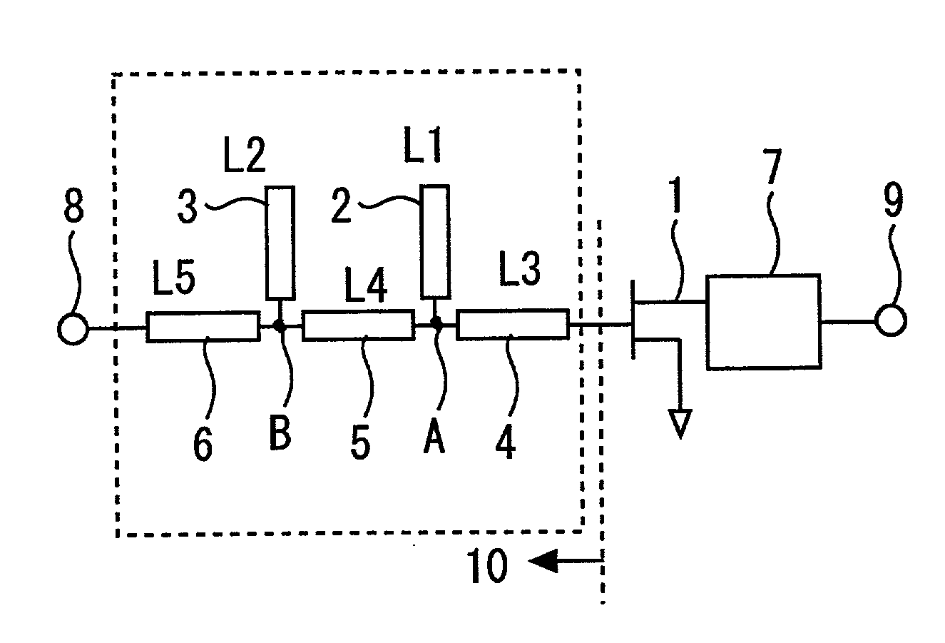
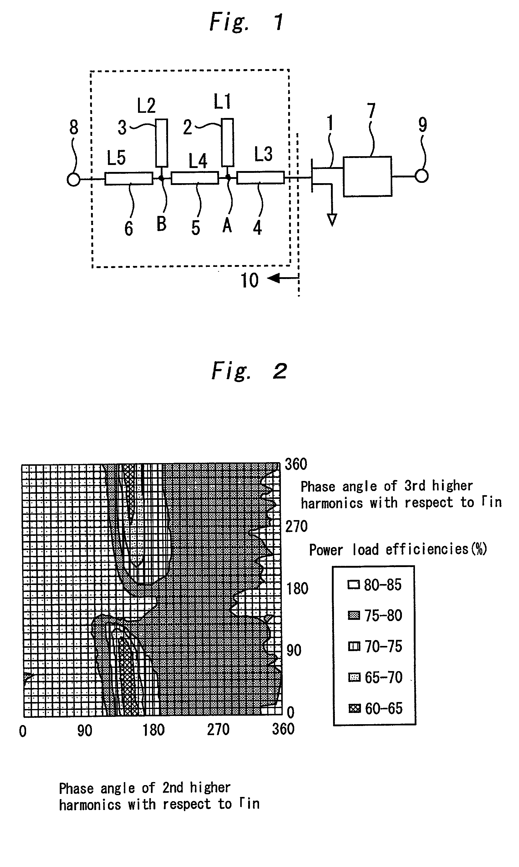
[0024] FIG. 1 shows a circuit configuration of a high frequency power amplifier in First Embodiment of the present invention. In FIG. 1, reference numeral 1 denotes a transistor, 2 denotes a signal line 1 (line length: L1, line width: W1), 3 denotes a signal line 2 (line length: L2, line width: W2), 4 denotes a signal line 3 (line length: L3, line width: W3), 5 denotes a signal line 4 (line length: L4, line width: W4), 6 denotes a signal line 5 (line length: L5, line width: W5), 7 denotes an output-side matching circuit, 8 denotes a signal input terminal, and 9 denotes a signal output terminal. If impedance is not matched in the middle or ends of signal lines 1 or the like, a part of the incident wave is reflected. The ratio of this reflected wave to the incident wave is called a reflection coefficient. In FIG. 1, reference numeral 10 denotes the reflection coefficient (.GAMMA.in) when the input-side matching circuit is viewed from the direction of the transistor 1. In general, the ...

second embodiment

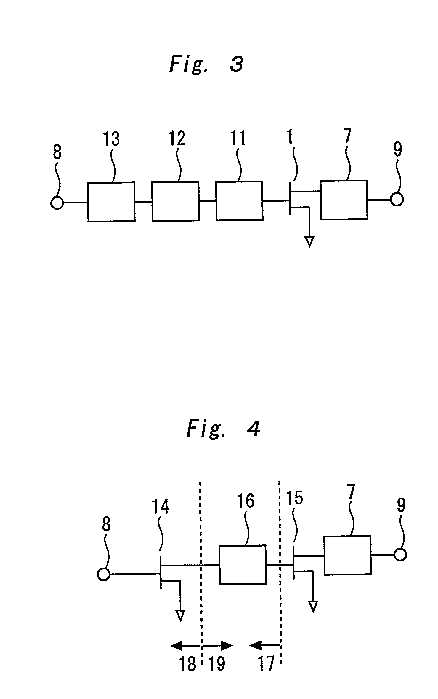
[0031] FIG. 3 shows a circuit configuration of a high frequency power amplifier in Second Embodiment of the present invention. In FIG. 3, since the same reference numerals as used in FIG. 1 denote the same elements, no description will be made for such elements. In FIG. 3, reference numeral 11 denotes an input-side fundamental wave matching circuit, 12 denotes an input-side 2nd higher harmonic processing circuit, and 13 denotes an input-side 3rd higher harmonic reflecting circuit. As FIG. 3 shows, the input-side fundamental wave matching circuit 11, the input-side 2nd higher harmonic processing circuit 12, and the input-side 3rd higher harmonic reflecting circuit 13 are connected in series. In order to improve the operation efficiency of the transistor 1 using the higher harmonic processing circuit 12, the phase angle of reflection, as well as the quantity of reflection must be increased. In general, there is the problem that the higher the frequency of a signal, that is, the higher...

third embodiment

[0033] FIG. 4 shows a circuit configuration of a high frequency power amplifier in Third Embodiment of the present invention. In FIG. 4, since the same reference numerals as used in FIG. 1 denote the same elements, no description will be made for such elements. In FIG. 4, reference numeral 14 denotes a front stage transistor, 15 denotes a rear stage transistor, 16 denotes an inter-stage matching circuit, 17 denotes an input-side reflection coefficient (.GAMMA.in 1) viewed from the direction of the rear stage transistor 15, 18 denotes an output-side reflection coefficient (.GAMMA.out 2) of the front stage transistor 14 viewed from the direction of the inter-stage matching circuit 16, and 19 denotes the reflection coefficient (.GAMMA. 2) of the front stage transistor 14 viewed from the direction of the inter-stage matching circuit 16.

[0034] As described above, higher harmonic loads are adjusted by reflection using a passive resonance circuit in the prior application. However, in Third...


PUM


Abstract

A high frequency power amplifier that can improve an efficiency of an operation of a transistor without limiting any input-side higher harmonic load of an impedance matching circuit to a short-circuit load, and can increase a quantity of reflection of higher harmonics. By adjusting line lengths L1 to L5 and line widths W1 to W5 of the signal lines 1 to 5, a 2nd higher harmonic can be adjusted to be an open load (a reflected phase angle of Γin: 0-90°, the quantity of reflection: 0.6-1.0), and a 3rd higher harmonic is adjusted to be a short-circuit load (the reflected phase angle of Γin:110-270°, the quantity of reflection: 0.6-1.0). By this optimization of an input-side higher harmonic load of the impedance matching circuit, an efficiency of transistor operation can be improved. By disposing a higher harmonic processing circuit 12 of higher orders closer to a transistor 1, there is provided a high frequency power amplifier with a shortened line length between the higher harmonic processing circuit 12 and the transistor 1, and increased quantity of reflection of higher harmonics.

Description

[0001] 1. Field of the Invention[0002] The present invention relates to a high frequency power amplifier, and more specifically, to a high frequency power amplifier used in microwave or millimetric-wave telecommunications equipment for mobile communications or satellite communications.[0003] 2. Description of Related Art[0004] In conventional high frequency power amplifiers used in microwave or millimetric-wave telecommunications equipment for mobile communications or satellite communications, it is well known that the efficiency of transistor operation is higher if the load at the frequencies of not only the fundamental waves but also higher harmonics of the output circuit of a transistor is controlled, as compared with the case where only the load of fundamental waves is controlled. Here, the fundamental waves are the waves that have the lowest frequency, and the higher harmonics are a series of waves, each of which has a frequency that is an integral multiple of the fundamental f...

Claims


Application Information

Patent Timeline
IPC IPC(8): H03F1/02H03F1/56H03F3/60H03F3/68
CPCH03F1/0205H03F3/604H03F1/565
Inventor GOTOU, SEIKIOHTA, AKIRA
Owner MITSUBISHI ELECTRIC CORP
Learn More