Payload delivery system

a payload and delivery system technology, applied in the field of payload delivery systems, can solve the problems of high cost associated with cargo size and weight, many payload delivery systems, while useful in particular circumstances, have limitations to their use in other circumstances, and the accuracy of systems acquiring and reaching targets is limited, so as to minimize the weight of the overall system

Inactive Publication Date: 2002-06-06
AEROVIRONMENT INC
View PDF0 Cites 29 Cited by
  • Summary
  • Abstract
  • Description
  • Claims
  • Application Information

AI Technical Summary

Benefits of technology

[0009] The invention includes an aircraft that defines flight vertical, lateral and fore-and-aft directions. The aircraft is configured with one or more components selected from a group of components. The group of components includes a fuselage having a fore-and-aft length dimension, an empennage having a vertical height dimension, and a wing having a lateral wingspan dimension. The invention features the one or more components being configured to unfold from a folded configuration to a deployed configuration that substantially increases its associated distance (i.e., the fuselage length, the wingspan and / or the empennage height).
[0011] The invention also features a fuselage that includes a forward fuselage portion and an aft fuselage portion configured to deflect relative to each other when the fuselage unfolds from a folded configuration to the deployed configuration. In deflecting, the forward and aft fuselage portions preferably rotate approximately 180.degree. relative to one another, in a substantially lateral fold-direction. Advantageously, this feature both reduces fuselage length and preferably places laterally wide portions of the empennage near the wing, thus efficiently placing wide components near each other.
[0013] The invention further features outboard wing portions that fold approximately 180.degree. preferably in a completely, or at least substantially, horizontal rotational direction. Preferably the outer wing portions fold under an inboard portion of the wing. The invention also features an empennage that folds down, preferably by approximately 90.degree. into a substantially horizontal plane. These features add to the volumetric efficiency of the folded aircraft.
[0014] Advantageously, the invention features a pod configured to contain the folded aircraft and to release it when it reaches a designated release location that allows the aircraft to acquire and reach a desired flight path and / or a desired destination. The pod is configured to protect the aircraft until it reaches the release location. The invention further includes a vehicle, such as a projectile, a rocket, an airplane, a satellite, spacecraft or the like, to deliver the pod to, and drop the pod from, a drop location above the release location, such that the pod can guide the aircraft from the drop location to the release location. The vehicle can be configured to carry a multitude of pods, each containing a payload, which could be of a wide variety of types, and could be the payload delivery system itself.
[0015] Advantageously, these features provide for the aircraft to be positioned to reach a desired target from a starting place that could be almost any distance away. Additionally, the efficient design provides for the delivery of a multitude of payloads to a variety of locations with only one launch vehicle, minimizing the weight of the overall system.

Problems solved by technology

This is particularly important if the payload delivery system is to be transported in space, which has high costs associated with cargo size and weight.
Many payload delivery systems, while useful in particular circumstances, have limitations to their use in other circumstances.
Some of these systems have limited accuracy on acquiring and reaching their targets.
Others are too large, heavy or otherwise impractical for certain missions.
Many payload delivery systems are not capable of accomplishing missions where the target is at very high altitudes, on other planets, or where the target is a pathway that covers extended distances.

Method used


Image

  • Payload delivery system
  • Payload delivery system
  • Payload delivery system

Examples


Embodiment Construction

[0029] The invention summarized above and defined by the enumerated claims may be better understood by referring to the following detailed description, which should be read in conjunction with the accompanying drawings. This detailed description of the preferred embodiments, set out below to enable one to build and use particular implementations of the invention, is not intended to limit the enumerated claims other than as set forth in the claims. Rather, it is intended to serve as a particular example thereof.

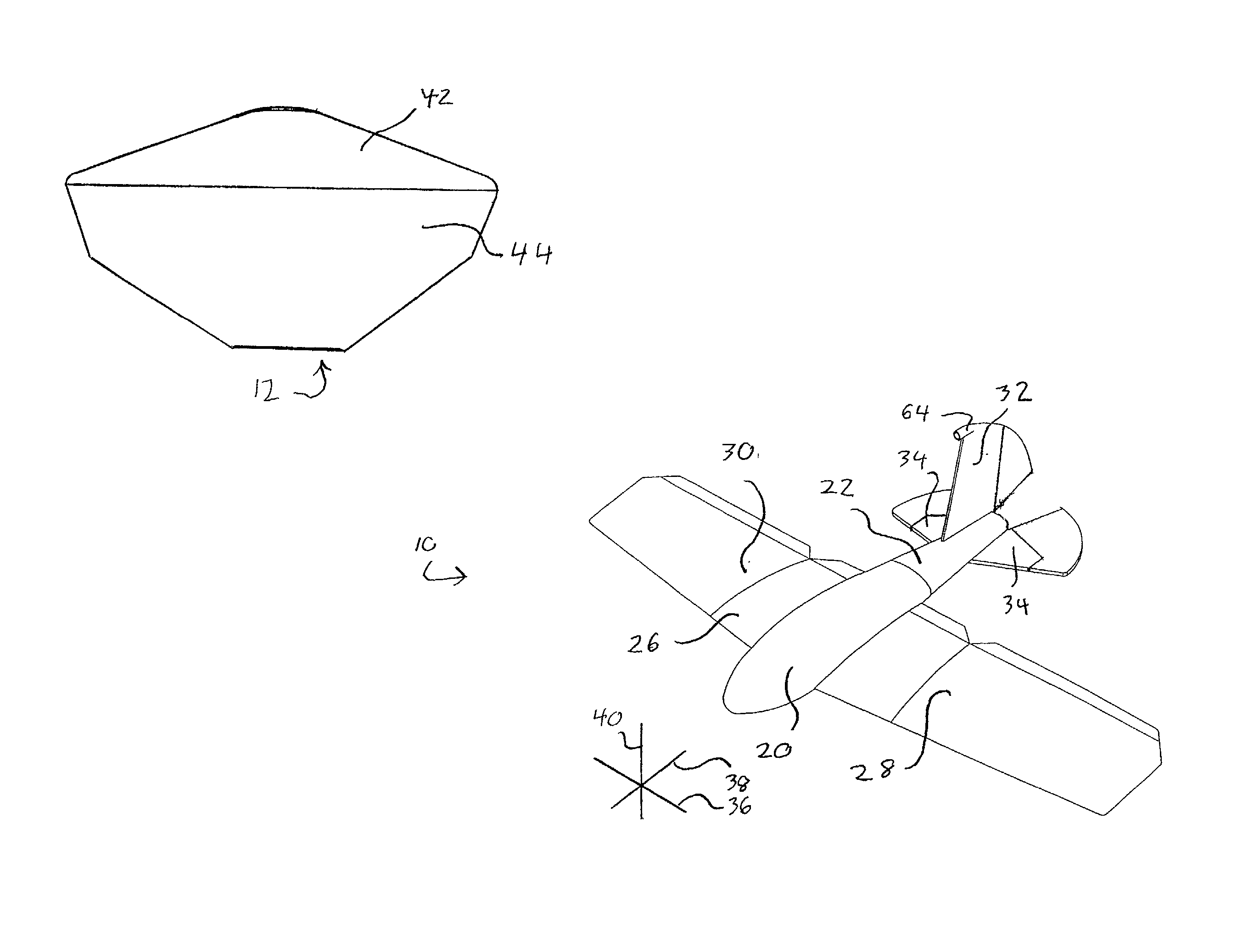
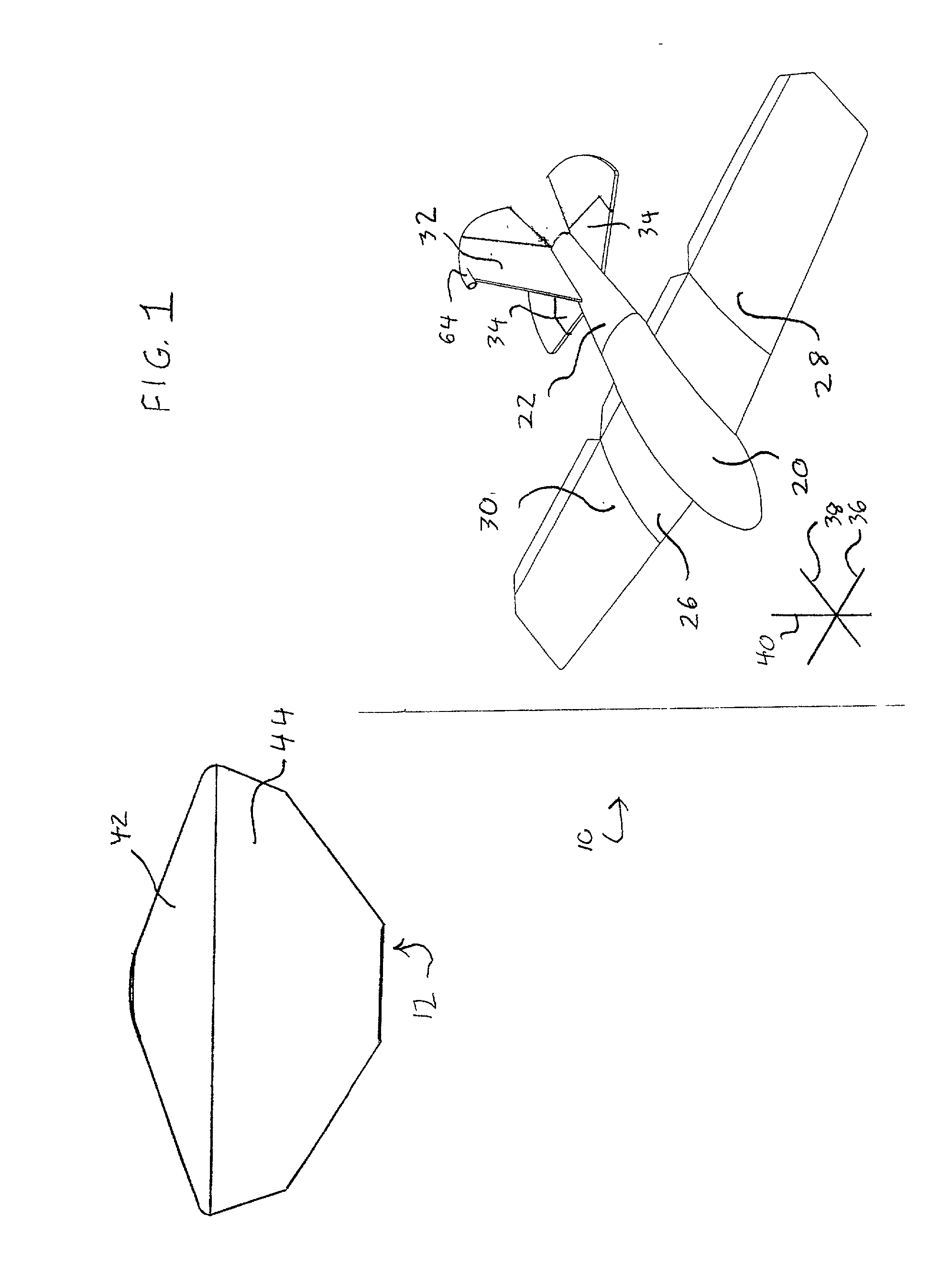
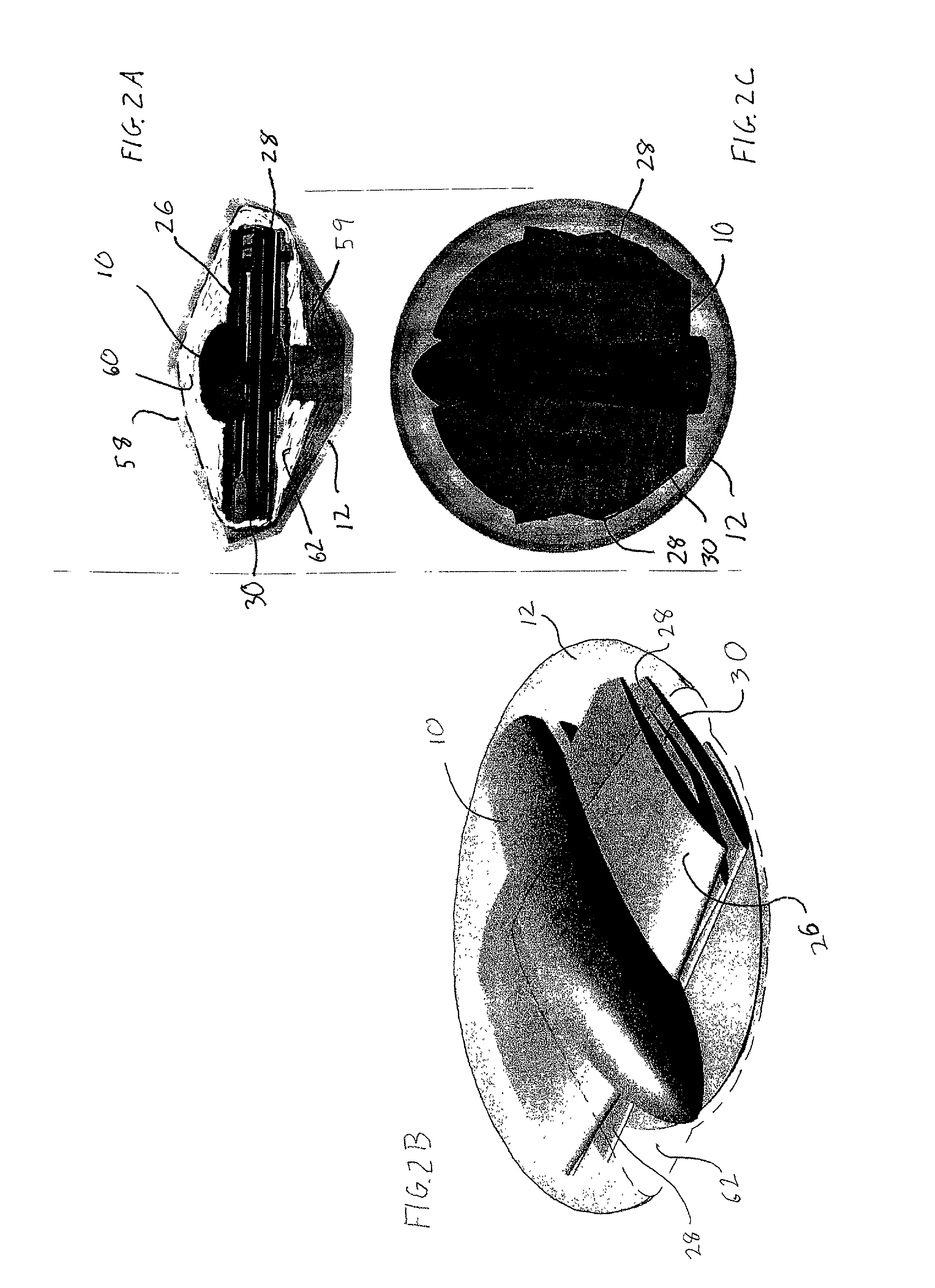
[0030] With reference to FIG. 1, a preferred embodiment of the invention is a system including an aircraft 10, which is preferably unpowered (i.e., a glider), and an aeroshell / pod 12. The aircraft defines lateral 36, for-and-aft 38 and vertical 40 directions that are typical for an aircraft reference frame. The pod includes an upper portion 42 and a lower portion 44.

[0031] The aircraft 10 includes a fuselage having a forward fuselage portion 20 and an aft fuselage portion 22, ...


PUM


Abstract

Disclosed is a spacecraft carrying a number of pods, each containing an aircraft that has been folded to fit in the pod. Each aircraft has a vertical stabilizer and outboard wing-portions that fold around fore-and-aft axes. Each aircraft also has a fuselage that folds around a lateral axis. The spacecraft releases one or more of the pods into an atmosphere. Each of the pods is configured with an ablative heat shield and parachutes to protect its aircraft when the pod descends through the atmosphere. The pod releases its aircraft at a desired altitude or location, and the aircraft unfolds while free-falling. The aircraft then acquires and follows a flight path, and activates scientific experiments and instruments that it carries. The aircraft relays results and readings from the experiments and instruments to the spacecraft, which in turn relays the results and readings to a mission command center.

Description

[0001] This application is a continuation-in-part of U.S. patent application Ser. No. 29 / 121,810, which is incorporated herein by reference for all purposes.[0002] The present invention relates to a payload delivery system. More particularly, the present invention relates to a drop vehicle configured for airborne flight-configuration deployment.BACKGROUND OF THE INVENTION[0003] Payload delivery systems are used to deliver a payload, either to a target location, or along a target pathway, or both. Airborne payload delivery systems are frequently used to deliver payloads to targets located in inhospitable or hard-to reach locations.[0004] Payload delivery systems must be designed with support structures and control systems that are adequate to deliver the payload in a manner that meets the physical and environmental needs of the payload. At the same time, payload delivery systems are preferably limited in size and weight, so as to minimize the carrying requirements on any launch syste...

Claims


Application Information

Patent Timeline
Patent Type & Authority Applications(United States)
IPC IPC(8): B64C1/30B64C3/56B64C39/02B64G1/10B64G1/22B64G1/62
CPCB64C1/30B64C2201/203B64C39/024B64C2201/042B64C2201/082B64C2201/102B64C2201/126B64C2201/127B64C2201/128B64C2201/141B64C2201/146B64C2201/148B64G1/105B64G1/222B64G1/62B64C2201/185B64C3/56B64U70/20B64U30/12B64U50/19B64U2101/00B64U2101/60B64U2101/30B64U2201/10B64U2201/20B64U2201/202B64U70/83B64U80/60
Inventor MIRALLES, CARLOS T.HIBBS, BART D.
Owner AEROVIRONMENT INC
Why Eureka
Try Eureka