Antenna device, communication apparatus and radar module

a technology of communication apparatus and antenna, applied in the direction of antenna details, antennas, antennas, etc., can solve the problems of significant deterioration in the side-lobe level, reducing the gain of the antenna, and unable to perform scanning in a wide angular range, etc., to achieve the effect of improving the directional accuracy of each dielectric lens and facilitating the assembly of dielectric lenses

Inactive Publication Date: 2002-06-06
MURATA MFG CO LTD
View PDF2 Cites 39 Cited by
  • Summary
  • Abstract
  • Description
  • Claims
  • Application Information

AI Technical Summary

Benefits of technology

0023] Furthermore, in this antenna device, the dielectric lenses may be integrally formed over the plurality of openings. This arrangement facilitates the assembly of dielectric lenses and improves the directional accuracy of each dielectric lens.
0024] According to a second aspect of the invention, there is provided a communi...

Problems solved by technology

On the other hand, in the device (1), when the displacement of the primary radiator is increased in order to perform beam scanning over a wide angular range by using the single dielectric lens and the single primary radiator, the position of the primary radiator significantly deviates from the most suitable position for the dielectric lens and the gain of the antenna is reduced, thereby resulting in significant deterioration in the side-lobe level (characteristics).
As a result, since the beam-scanning angle cannot be changed widely, scanning cannot be perfo...

Method used


Image

  • Antenna device, communication apparatus and radar module
  • Antenna device, communication apparatus and radar module
  • Antenna device, communication apparatus and radar module

Examples


first embodiment

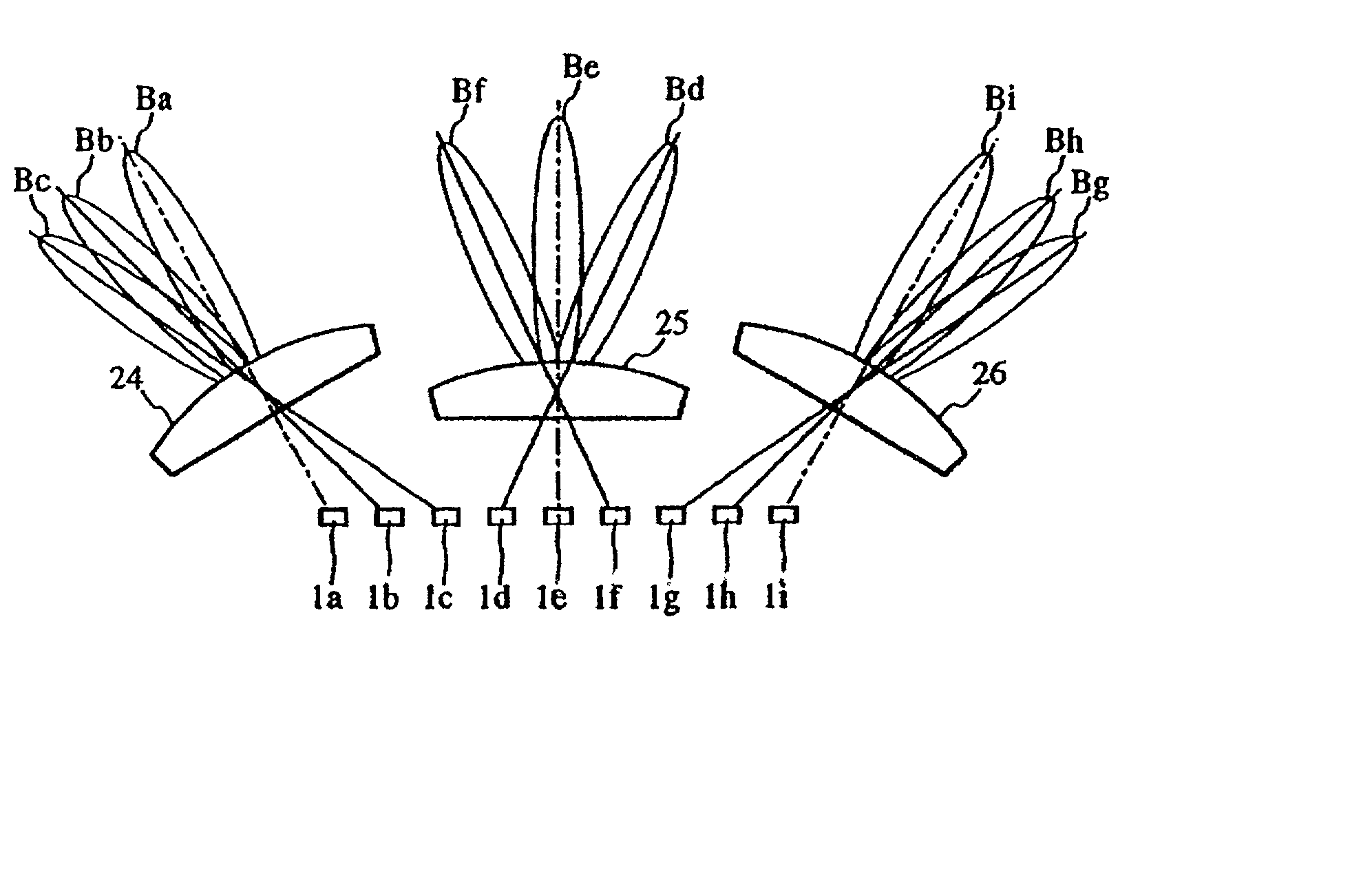
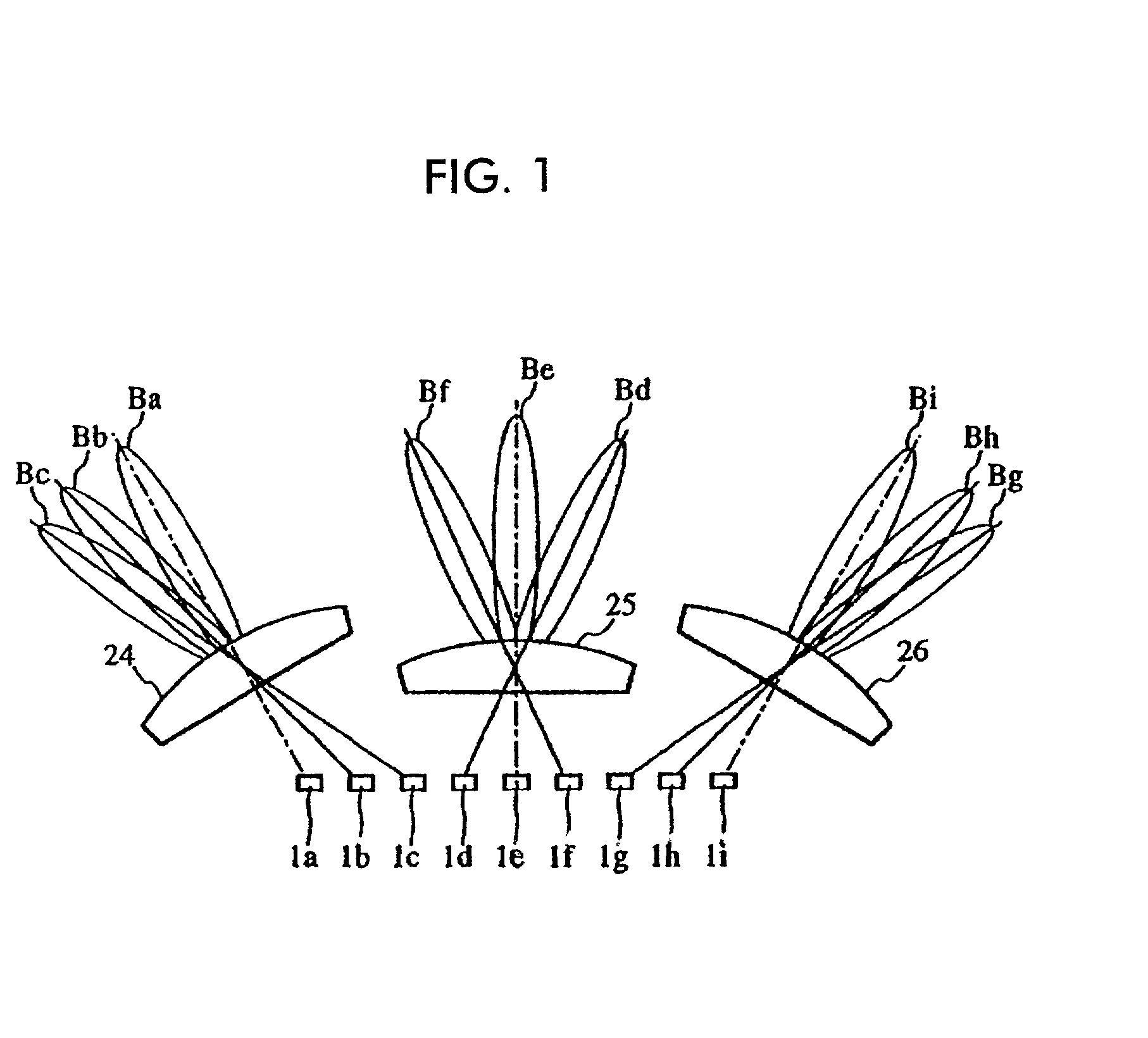
[0043] With reference to FIGS. 1 to 3, a description will be given of the structure of an antenna device according to the present invention.

[0044] FIG. 1 illustrates the main part of the antenna device and an example of the displacement of a primary radiator obtained when performing beam scanning. Actually, the antenna device has a single primary radiator. The reference numerals 1a to 1i shown in FIG. 1 indicate the positions of a primary radiator 1 when beam scanning is performed. As will be described below, a primary radiator 1 is displaced with a mechanism in which a rotary motor or a linear motor is used as a driving source. The reference characters Ba to Bi represent the directional patterns of the antenna obtained when the primary radiator 1 is in the positions 1a to 1i. The patterns will simply be referred to as beams below.

[0045] The reference numerals 24, 25, and 26 denote dielectric lenses converging electromagnetic waves whose radiation intensities are distributed in a re...

second embodiment

[0056] Next, an antenna device according to the invention will be described with reference to FIG. 4.

[0057] In the first embodiment, in the linear displacement of the primary radiator, by geometrically changing the position of the primary radiator with respect to the center of each of the dielectric lenses, the direction in which a beam is oriented is changed. However, in the embodiment shown in FIG. 4, the primary radiator 1 is rotationally displaced. In other words, for example, when the radiation pattern (hereinafter referred to as a radiated beam) of an electromagnetic wave radiated from the primary radiator 1 is represented by Be', the dielectric lens 25 converges the radiated beam to form a beam Be in the forward direction. When the primary radiator 1 rotates at a predetermined angle in a clock-wise direction in the figure and a beam radiated from the primary radiator is represented by Bf', a beam radiated in the forward direction via the dielectric lens 25 is represented by B...

third embodiment

[0060] Next, an antenna device according to the invention will be described with reference to FIGS. 5A and 5B.

[0061] In each of the first and second embodiments, the dielectric lenses placed on the right and left are arranged in such a manner that the central axes of the three dielectric lenses pass near the center of the scanning range of the primary radiator or near the position of the primary radiator. However, as shown in FIG. 5A, the dielectric lenses may be arranged in such a manner that the central axes of the dielectric lenses 24, 25, and 26 are parallel to each other.

[0062] In addition, in each of the first and second embodiments, the three dielectric lenses have substantially equal aperture sizes. However, as shown in Fig. 5B, for example, the aperture or opening of the dielectric lens 25 in the forward direction may be larger than the apertures of the remaining dielectric lenses 24 and 26. In this manner, by making the aperture of the dielectric lens 25 used for forming a...


PUM


Abstract

An antenna device capable of increasing the speed of scanning as well as extending the scanning angular range of a beam to obtain a high gain. A radar module and a communication apparatus having enhanced detection capabilities obtainable by using the antenna device. In the antenna device, electromagnetic waves radiated from a primary radiator are transmitted to a plurality of openings, e.g., dielectric lenses and/or reflectors or optical transmitters. The dielectric openings are arranged on a fixed portion and the primary radiator is arranged on a moving portion. The moving portion is displaced relatively with respect to the fixed portion. This arrangement enables the selection of an opening used for receiving each of the electromagnetic waves from the primary radiator to change the direction of the beam.

Description

[0001] 1. Field of the Invention[0002] The present invention relates to antenna devices with primary radiators and openings, used for transmission in millimeter-wave bands. The invention also relates to communication apparatus and radar modules incorporating the antenna devices.[0003] 2. Description of the Related Art[0004] In a conventional vehicle radar module utilizing a millimeter wave band or the like, a radar beam having high directivity is emitted in the forward and backward directions of the vehicle. Then, the radar module receives waves reflected by targets such as other vehicles running before and after the vehicle to detect distances from the targets and the relative speed of the vehicle with respect to the targets based on the time lag and the frequency difference between transmitted and received signals. In such a millimeter-wave radar module, when the angular range of detection is narrow, the beams of transmitted and received waves will be formed in fixed directions. H...

Claims


Application Information

Patent Timeline
IPC IPC(8): H01Q1/32H01Q19/00H01Q3/04H01Q3/14H01Q3/24H01Q13/24H01Q19/06H01Q21/20H01Q25/00
CPCH01Q1/3233H01Q25/007H01Q19/062H01Q3/14H01Q19/00
Inventor TAKIMOTO, YUKIOTANIZAKI, TORUNAKAMURA, FUMINORITAKAKUWA, IKUOKITAMORI, NOBUMASA
Owner MURATA MFG CO LTD
Why Eureka
Try Eureka