Densifying hollow porous substrates by chemical vapor infiltration

a technology of hollow porous substrates and chemical vapor infiltration, which is applied in the direction of liquid surface applicators, chemical vapor deposition coatings, coatings, etc., can solve the problems of spoiling the properties of the substrate, soot or undesirable projections on the substrate, and defects observed by the substrate, etc., to achieve the effect of free from defects

Inactive Publication Date: 2002-06-20
GERAKL
View PDF7 Cites 19 Cited by
  • Summary
  • Abstract
  • Description
  • Claims
  • Application Information

AI Technical Summary

Benefits of technology

0010] An object of the invention is to provide a method which does not present such drawbacks, i.e. a method that enables hollow

Problems solved by technology

When the substrates to be densified are hollow as defined above, having relatively deep concave portions, and in particular when they are of quite large dimensions, defects have been observed by the inventors after densification by chemical vapor infiltration.
These defects consist in variations in the microstructure of the material of the matrix between different portions of the densified parts, and in the formation of soot or undesirable projections on the substrates.
Since these defects can

Method used


Image

  • Densifying hollow porous substrates by chemical vapor infiltration
  • Densifying hollow porous substrates by chemical vapor infiltration
  • Densifying hollow porous substrates by chemical vapor infiltration

Examples


example

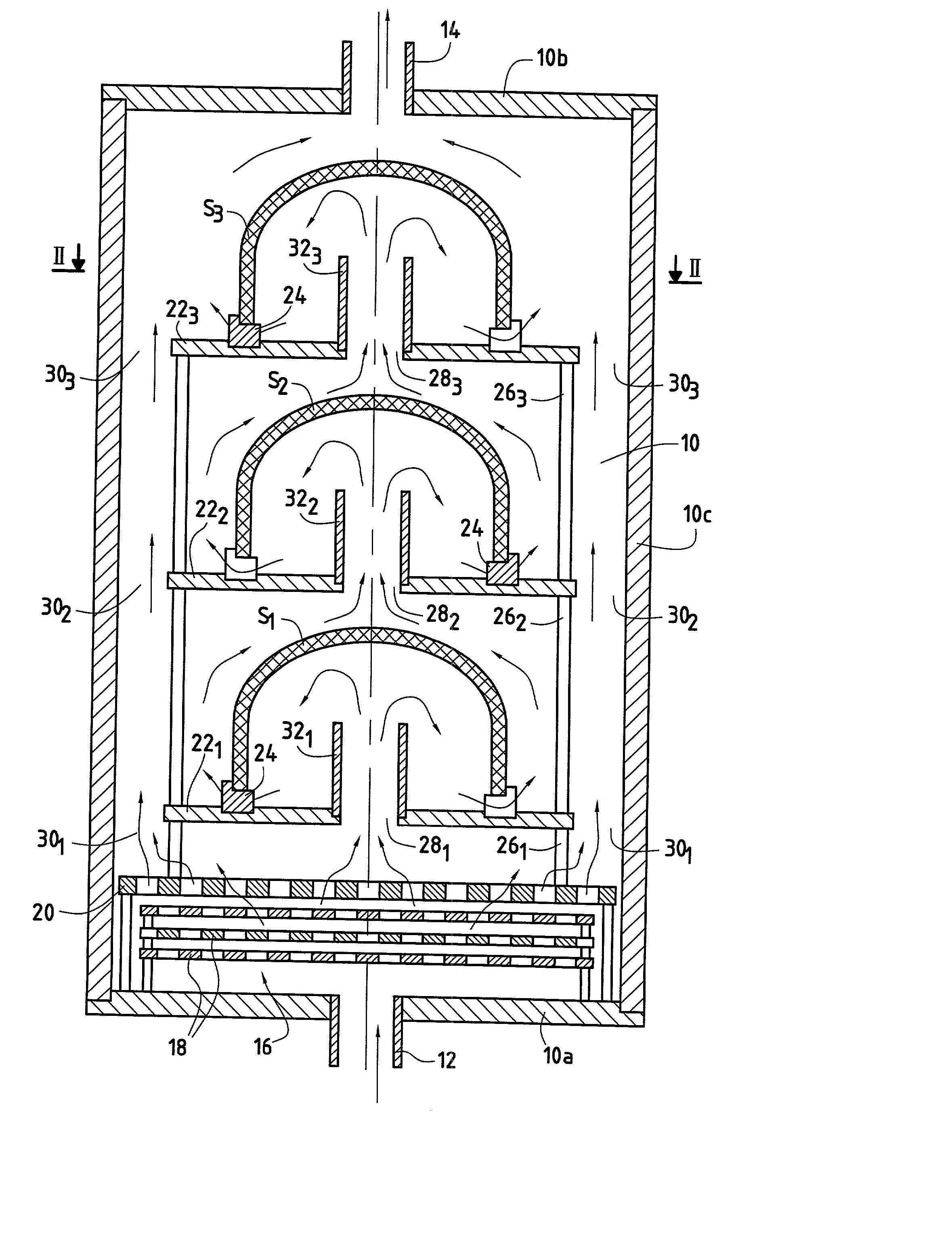
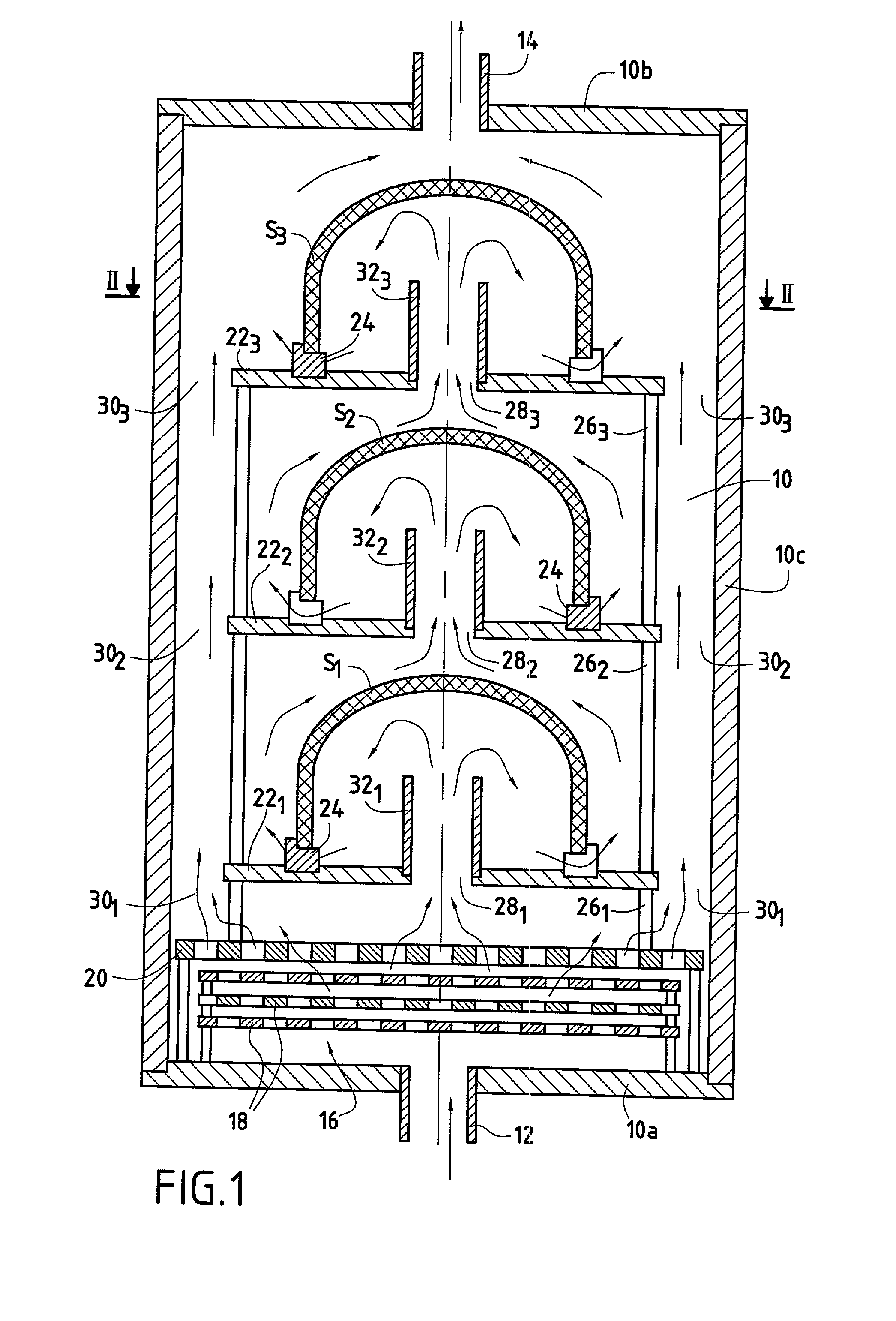
[0085] Substrates constituted by bowl preforms were densified using an installation of the kind shown in FIG. 7. The substrates were built up from two-dimensional carbon fiber plies draped onto a shaper and consolidated by being impregnated with a resin followed by polymerization and carbonization of the resin.

[0086] The substrates were densified with a matrix of pyrolytic carbon by admitting a gas into the enclosure comprising natural gas or methane as the gaseous precursor for pyrolytic carbon.

[0087] The temperature and the pressure inside the enclosure were maintained substantially constant throughout the densification process, at values equal to about 1000.degree. C. and 1.5 kilopascals (kPa).

[0088] Once densification had been completed, no projections or soot formations were observed. The inside faces of the resulting C / C composite material bowls were of good appearance, as shown in FIGS. 9 and 10 where FIG. 10 is an image obtained using an optical microscope, with .quadrature....


PUM

PropertyMeasurementUnit
Fractionaaaaaaaaaa
Fractionaaaaaaaaaa
Pressureaaaaaaaaaa

Abstract

Part of the flow of reactive gas admitted into the enclosure (10) is guided to the inside of the volume defined by a concave inside face of the or each hollow-shaped substrate (S1, S2, S3) so that said concave inside face is swept in full by a fraction of the total admitted gas flow.

Description

[0001] The invention relates to densifying hollow porous substrates by chemical vapor infiltration (CVI), and more particularly doing so at pressure equilibrium, i.e. without any pressure gradient between the faces of the substrates.[0002] A particular field of application for the invention is making hollow parts out of a composite material comprising a porous substrate densified by a matrix, and in particular hollow parts made out of a thermostructural composite material.[0003] The term "hollow porous substrate" is used herein to mean a substrate of hollow shape having a concave inside surface that is continuous, i.e. that does not have any holes, other than those due to the porous nature of the substrate. Examples of hollow shapes are spherical cap shapes, cylindrical or cylindro-conical shapes that are closed at one end, receptacle or bowl shapes, and cover shapes, not necessarily axially symmetrical. Examples of hollow parts obtained by densifying such substrates are receptacles...

Claims


Application Information

Patent Timeline
IPC IPC(8): C04B35/83C04B41/85C23C16/04C23C16/26
CPCC04B35/83Y10S427/10C23C16/26C23C16/045
Inventor DELPERIER, BERNARDDOMBLIDES, JEAN-LUCRICHARD, JEAN-PHILIPPEDELAURENS, PIERRE
Owner GERAKL
Why Eureka
Try Eureka