Carrier and developer for electrostatic image development, and image formation method and apparatus

a carrier and electrostatic image technology, applied in the field of carrier and developer for electrostatic image development, can solve the problems of carrier breakage, insufficient fluidity, and inability to prevent complete carrier breakage, etc., to achieve the effect of increasing the fluidity of the carrier, suppressing the adhesion of an external additive, and stabilizing charge and/or resistan

Inactive Publication Date: 2007-01-25
FUJIFILM BUSINESS INNOVATION CORP
View PDF13 Cites 18 Cited by
  • Summary
  • Abstract
  • Description
  • Claims
  • Application Information

AI Technical Summary

Benefits of technology

[0036] The first, fourth to sixth and ninth aspects of the invention can provide a carrier for electrostatic image development, an image formation method, and an image formation apparatus having an increased fluidity of a carrier, which prevents the carrier to be broken into power, which causes formation of images having missing portions.
[0037] The third and eighth aspects of the invention can provide a developer for electrostatic image development which suppresses adhesion of an external additive to a carrier, stabilizes charge and / or resistance for a long period of time and enables output of high quality images.
[0038] The second and seventh aspects of the invention can provide a developer for electrostatic image development which suppresses peeling of the coating resin of a carrier which peeling often occurs with passage of time in conventional carriers, and adhesion of the carrier to a latent image-holding member and therefore enables formation of high quality images free from defects.

Problems solved by technology

In addition, to cut costs, it is necessary to prolong the life of the consumable parts.
However, the fluidity is insufficient and carrier breakage cannot be prevented completely.
However, the external additive agent with a small particle size undesirably separates from the toner and migrates to the carrier.
However, the frictional electric charge decreases in this method.
Therefore, when high density images are continuously outputted, density reproducibility deteriorates and fogging occurs.
Further, when the rate of the new carrier supplied to the developer (tricle) is low or no supply is newly carried out, contamination due to the external additive cannot be prevented completely during long-term use.
However, if a soft substance like a wax exists on the carrier surface, the fluidity of the carrier decreases, which leads to occurrence of toner concentration unevenness in the developing unit, particularly at a high temperature and a high humidity.
Further in the case of a two-component developer, the charging property of the carrier decreases along with the contamination of the carrier surface by the toner components, which may cause fogging and toner crowding.
In addition, the coating resin peels off from the carrier surface, which makes core particles with low resistance partially bare, decreases the resistance of the developer, and increases the amount of the carrier undesirably adhering to the latent image-holding member owing to the injection of the electric field in the development zone to such a developer.
In this case, if the carrier particle diameter is not changed, the toner coating rate on the carrier surface is so high as to make it impossible to electrically charge the toner sufficiently, and toner crowding or fogging tends to often occur.
However, making the carrier particle diameter small can increase the surface area per unit weight, but decreases the magnetic force of each carrier particle.
Therefore, the force of constraint by the magnetic field of the developer carrier weakens and the amount of the carrier adhering to the latent image-holding member consequently increases.
Therefore, the degree of the influence of the effective electric field in a development zone on a latent image-holding member becomes too large.
Further, after development, the electric charge with the opposite polarity to that of the toner which remains on the carrier cannot quickly escape to a developer-carrying member and image quality at the boundary of a high density portion and a low density portion worsens.
Consequently, a developer containing such carrier and toner cannot satisfy the demands for high image quality of recent years.
Therefore, stirring stress over a long duration causes the resin covering the surfaces of the carrier particles contained in the developer to gradually peel off.
As a result, peeling of the coating resin of the carrier often occurs, causing a significant decrease in the resistance of the carrier.
The peeling of the coating resin of the carrier does decrease the carrier resistance.
However, resistance continues to decrease during continuous use of the carrier and finally reaches a level at which charge injection is induced.
Consequently, charge is undesirably injected to the carrier and the carrier adheres to the latent image-holding member.
Considering this fact, the carrier of this document is also insufficient in wear resistance and in suppression of carrier adhesion.

Method used


Image

  • Carrier and developer for electrostatic image development, and image formation method and apparatus
  • Carrier and developer for electrostatic image development, and image formation method and apparatus
  • Carrier and developer for electrostatic image development, and image formation method and apparatus

Examples


example 1

[0276] Ferrite particles (including Cu—Zn and having a density of 4.5 g / cm3, a volume average particle diameter of 35 μm, and a shape factor SF1 of 125) are classified with an elbow-jet device (Product No. EJ-LABO manufactured by Nittetsu Mining Co., Ltd.) at cut points of 25 μm and 45 μm to remove powder and coarse powder and to obtain core particles to be coated.

[0277] Regarding the particle diameter distribution of the obtained core particles to be coated, the particle size distribution index at a coarse particle side (D84V / D50V) is 1.18, and the particle size distribution index at a particle size (D50P / D16P) is 1.20, and the volume average particle diameter is 37 μm, and the shape factor SF1 is 124.

[0278] Twenty parts by mass of a toluene solution (solid content of 15 parts by mass) of styrene-methyl methacrylate copolymer (weight-average molecular weight of 80,000) is added to 100 parts by mass of the core particles to be coated. The resultant mixture is stirred by a batch-ty...

examples 2 to 4

[0283] Carriers (2) to (4) are produced in the same manner as in Example 1, except that the number of repeated times of the powder / coarse powder removal treatment conducted with the elbow-jet device to obtain a carrier coated with a resin is changed from three to a value within the range of 2 to 5. The total energy amount of each of the carriers (2) to (4) is shown in Table 1.

example 5

[0284] Ferrite particles (including Cu—Zn and having a density of 4.5 g / cm3, a volume average particle diameter of 35 μm, and a shape factor SF1 of 120) are classified with the elbow-jet device at cut points of 22 μm and 45 μm to remove powder and coarse powder and to obtain core particles to be coated.

[0285] Regarding the particle diameter distribution of the obtained core particles to be coated, the particle size distribution index at a coarse particle side is 1.18, and the particle size distribution index at a particle size is 1.20, and the volume average particle diameter is 37 μm, and the shape factor SF1 is 118.

[0286] Sixty parts by mass of a toluene solution (solid content of 5% by mass) of methyl methacrylate-perfluorohexyl acrylate copolymer (having a copolymerization rate of the former monomer to the latter monomer of 80 / 20, and a weight-average molecular weight of 50,000, and manufactured by Sanyo Chemical Industries Ltd.) and 10 parts by mass of a toluene solution (sol...


PUM


Abstract

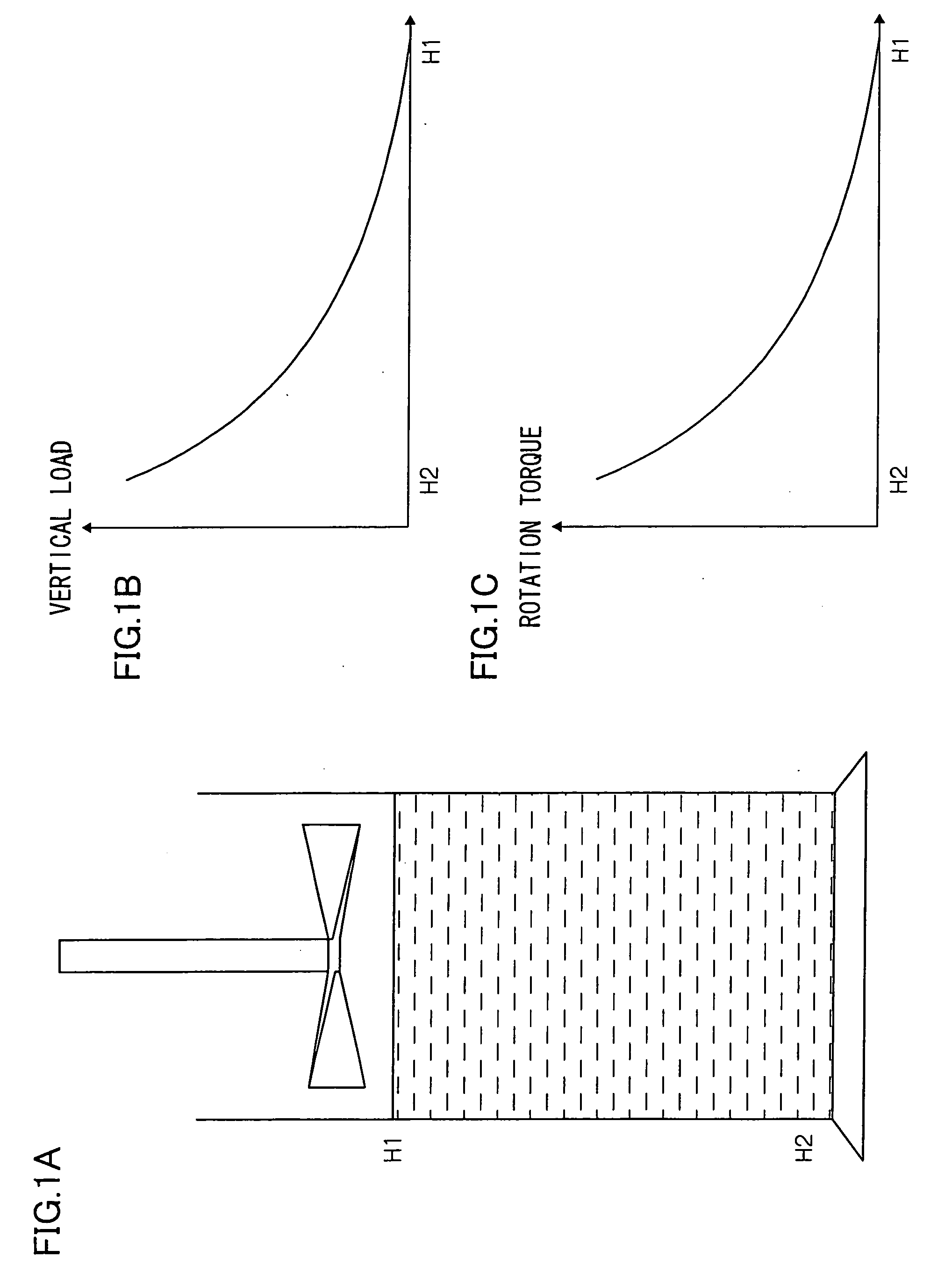
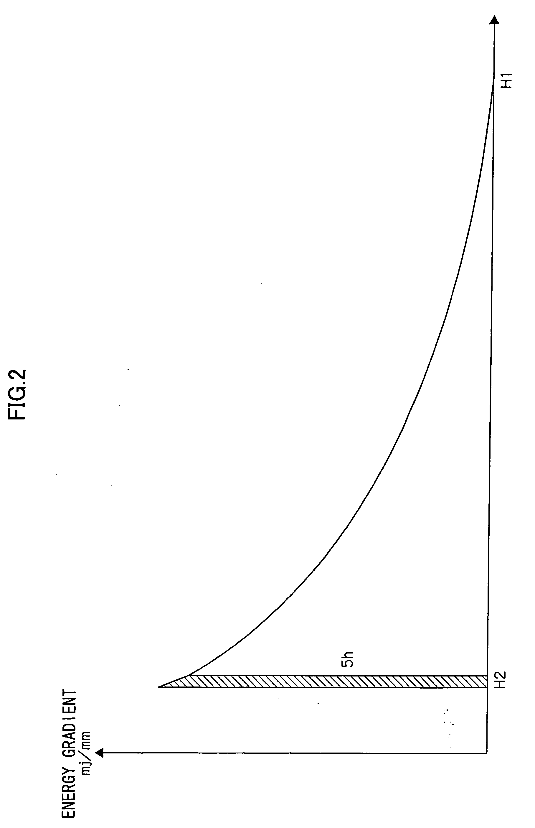
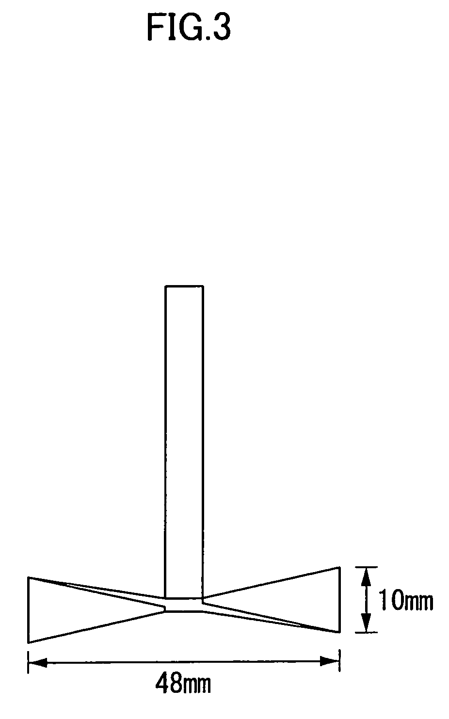
The present invention provides a carrier for electrostatic image development, and a developer, an image formation method and an image formation apparatus using the carrier. The carrier is carrier particles. When the carrier particles each have a coating layer on a magnetic particle, the carrier has a total energy amount of 1500 to 3000 mJ. When the carrier particles each have a coating layer on a magnetic powder-dispersed particle, the carrier has a total energy amount of 1000 to 1500 mJ. The total energy amount is measured with a powder rheometer at a tip end speed of a rotor of 100 mm/s and a helix angle of the rotor of −5°. The total energy amount is a value of a portion of the carrier in a measurement container which portion is contained in the region between the packed surface of the carrier and a surface disposed under the packed surface by 70 mm.

Description

CROSS-REFERENCE TO RELATED APPLICATION [0001] This application claims priority under 35 USC 119 from Japanese Patent Application Nos. 2005-215154, 2005-215158, and 2005-237879, the disclosures of which are incorporated by reference herein. BACKGROUND OF THE INVENTION [0002] 1. Field of the Invention [0003] The present invention relates to a carrier for electrostatic image development, a developer for electrostatic image development, an image formation method, and an image formation apparatus to be used for development of electrostatic latent images by, for example, an electrophotographic method or an electrostatic recording method. [0004] 2. Description of the Related Art [0005] A method for visualizing image information through electrostatic latent images by electrophotography is presently employed in various fields. In electrophotography, an image is obtained by forming an electrostatic image on a photoconductor (a latent image-holding member) in charging and exposing steps; devel...

Claims


Application Information

Patent Timeline
Patent Type & Authority Applications(United States)
IPC IPC(8): G03G9/113
CPCG03G9/0827G03G9/09708G03G9/0833G03G9/1134G03G2215/0607G03G9/1075
Inventor MATSUMOTO, AKIRAIIZUKA, AKIHIROFUKUDA, HIROYUKIKIYONO, FUSAKOYANO, TOSHIYUKI
Owner FUJIFILM BUSINESS INNOVATION CORP
Why Eureka
Try Eureka