Supercharge Your Innovation With Domain-Expert AI Agents!

Wire bonding capillary

a wire bonding capillary and wire bonding technology, applied in the direction of non-electric welding apparatus, electrical equipment, soldering auxiliaries, etc., can solve the problems of increasing the drag force of the wire in the capillary, delay in the ic's production line, and the capillary does not provide a solution to the clogging problem

Inactive Publication Date: 2002-06-27
KESSEM TRADE
View PDF0 Cites 15 Cited by
  • Summary
  • Abstract
  • Description
  • Claims
  • Application Information

AI Technical Summary

Benefits of technology

0027] FIGS. 1(a)-1(g) show the steps of conventional prior art wire bonding technique.

Problems solved by technology

When this clearance becomes too tight, the drag force of the wire in the capillary increases until the capillary becomes clogged.
This is a costly process, and also causes delays in the IC's production lines.
However, even these capillaries do not provide a solution to the clogging problem when softer bond wires such as gold or aluminum are used.
Another problem with existing capillaries is that after certain service time, even before the end of their life span, the face of the capillary tip, which presses the wire or the molten ball against the finger lead or against the pad respectively, becomes contaminated with an accumulated layer of material which is much softer then alumina.
This phenomenon, which occurs prior to the clogging of the capillary, yields already at earlier stages bonds with inferior properties.

Method used


Image

  • Wire bonding capillary
  • Wire bonding capillary
  • Wire bonding capillary

Examples


Embodiment Construction

[0030] The present embodiment herein is not intended to be exhaustive and to limit in any way the scope of the invention, rather it is used as examples for the clarification of the invention and for enabling of other skilled in the art to utilize its teaching.

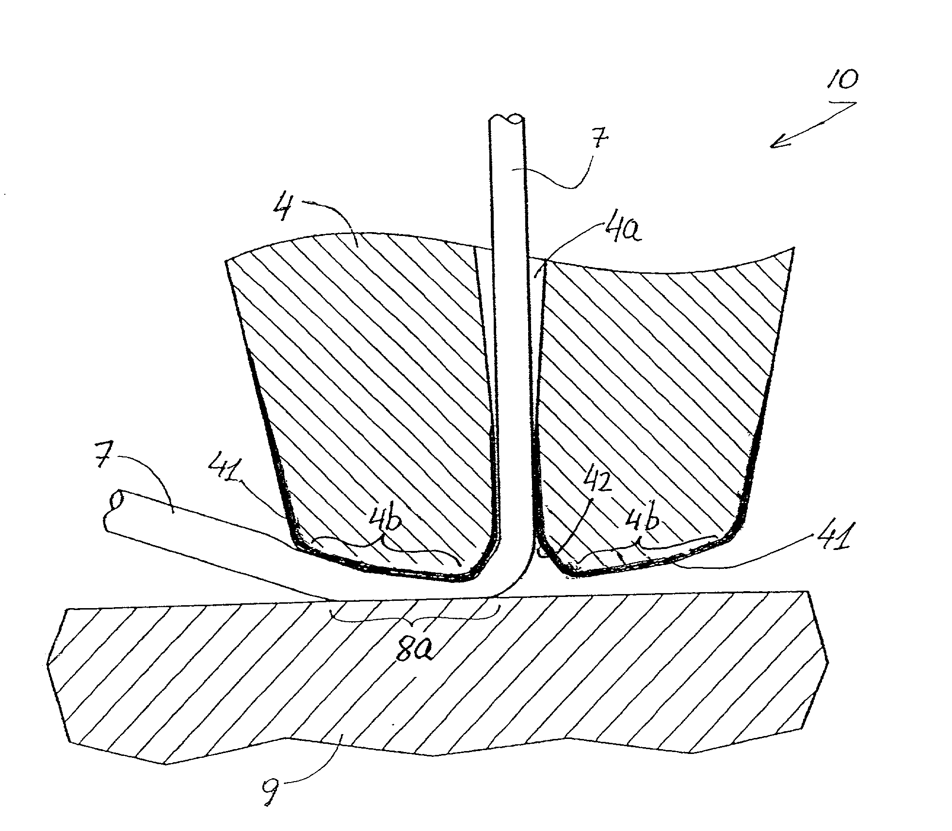
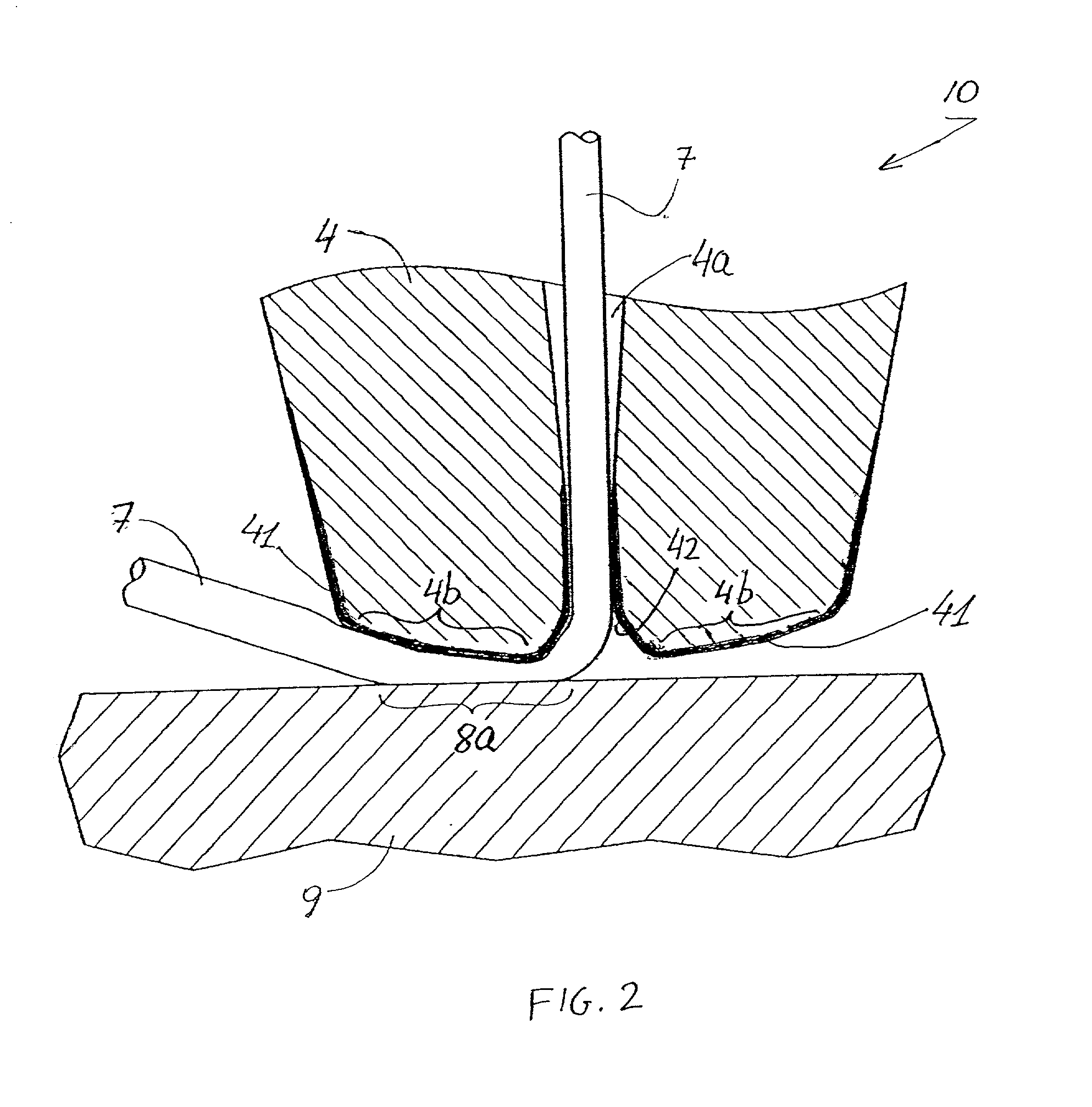
[0031] The present invention describes an improved capillary for wire bonding (either ball or wedge bonding).

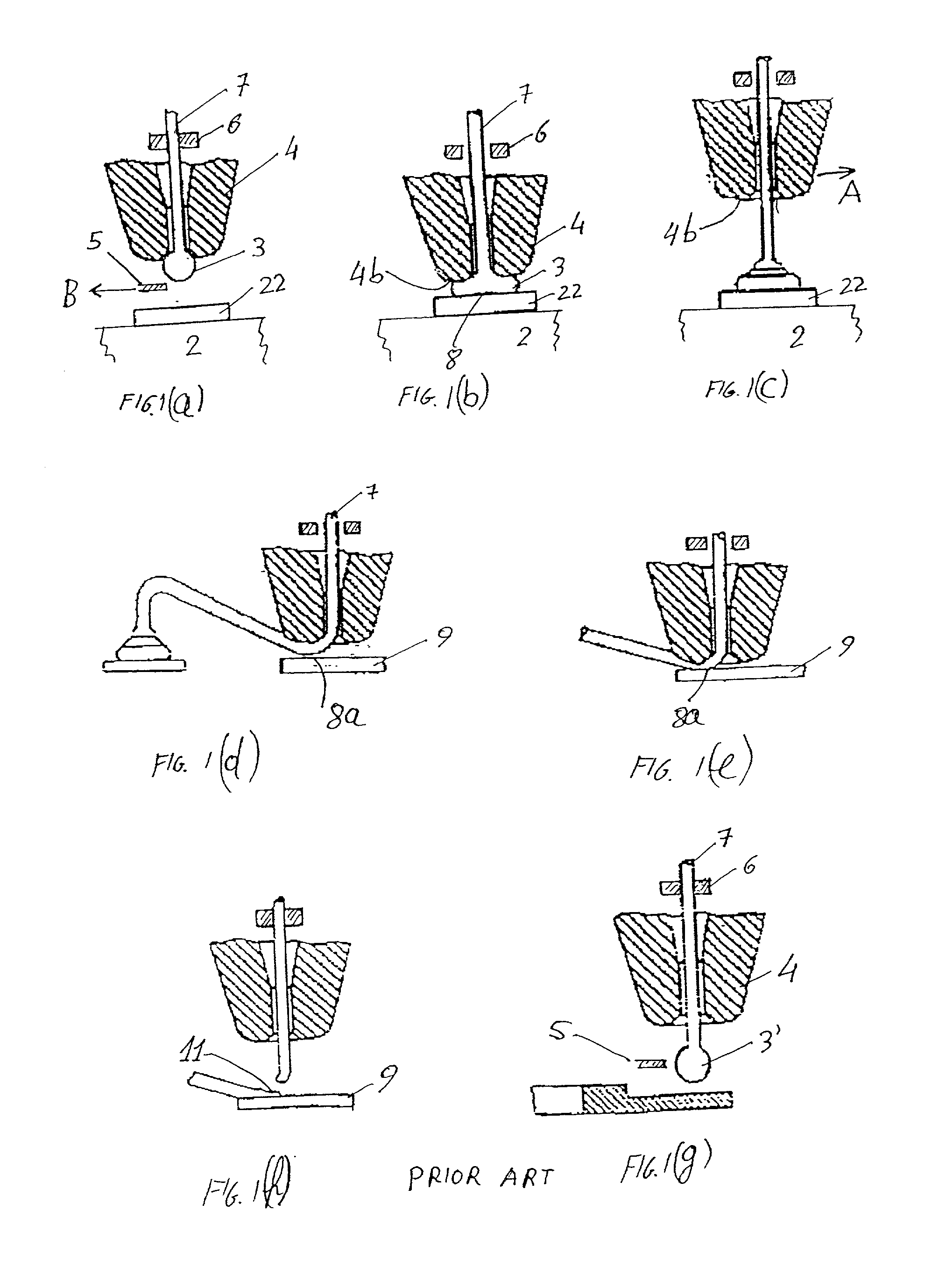
[0032] Wire bonding is a prior art technique which include the following stages: First, as shown in FIG. 1(a), a capillary 4, through which bonding wire 7 is threaded, is targeted over a the die 2 and positioned above bond pad 22. At this stage wire clamps 6 are closed. A ball 3 is formed by a spark discharge created by an electric torch 5 on part of wire 7, which extends from the lower end of a capillary 4. Electric torch 5 is there moved aside in the direction shown by arrow B.

[0033] Next, as shown in FIG. 1(b), the wire clamps 6 open and the capillary 4 is lowered. The ball 3 on the tip end of the wire 7 is pressed ag...


PUM

PropertyMeasurementUnit
temperatureaaaaaaaaaa
diameteraaaaaaaaaa
diameteraaaaaaaaaa

Abstract

A wire bonding capillary having an extended service life-time, the use of which results in bonds with improved and stable qualities. The capillary includes a polymeric film which is vapor phase polymerized on the out side of the capillary tip in which a threaded bond wire travels. The polymeric film prevents bond deterioration and capillary clogging by layers of contaminates which originate from the wire and the capillary manufacturing processes, and which would otherwise accumulate inside the bore and on the face of the tip of the capillary.

Description

[0001] This is a continuation-in-part of U.S. patent application Ser. No. 09 / 534,970 filed Mar. 27, 2000, now pending.FIELD AND BACKGROUND OF THE INVENTION[0002] The present invention relates to a method and an apparatus for mounting a semiconductor device onto a lead-frame, and more particularly to an improved wire bonding capillary provided for a wire bonding apparatus and a method of forming electric connection contacts which electrically connect metal bond pads formed on a semiconductor die to the lead fingers of a lead frame.[0003] Wire bonding devices are well known in the art. U.S. Pat. Nos. 3,894,671 issued to Kulicke Jr., et al., 4,877,173 issued to Fujimoro, et al., and 5,082,154 issued to Ishizuka illustrate known bonding devices.[0004] The wire bonding process occurs during the final stages of manufacture when the semiconductor device is enclosed within a sealed package. Although a variety of different packaging systems are used in the semiconductor industry, most system...

Claims


Application Information

Patent Timeline
Patent Type & Authority Applications(United States)
IPC IPC(8): B23K20/00
CPCB23K20/004H01L24/45H01L2924/14H01L2924/01082H01L2924/01079H01L2924/01046H01L2924/01028H01L2924/01015H01L2924/01013H01L2924/01006H01L2924/01005H01L2224/85205H01L2224/85181H01L2224/85045H01L2224/85043H01L2224/78302H01L2224/48465H01L2224/48247H01L2224/48091H01L2224/45144H01L2224/45124H01L24/85H01L24/78H01L2924/00014H01L2924/00H01L2224/45015H01L24/48H01L2924/20752H01L2924/00015
Inventor MACOVER, ERAN
Owner KESSEM TRADE
Features
  • R&D
  • Intellectual Property
  • Life Sciences
  • Materials
  • Tech Scout
  • Unparalleled Data Quality
  • Higher Quality Content
  • 60% Fewer Hallucinations
Learn More