Method for producing high quality optical parts by casting

a technology of optical parts and casting, applied in the direction of optical articles, domestic applications, other domestic objects, etc., can solve the problems of limited use of plastic in more demanding applications, insufficient weight reduction, and difficulty in reducing the weight of requiring bonding glass to plastic, etc., to achieve the effect of improving quality and quality

Inactive Publication Date: 2006-08-31
GOOGLE LLC
View PDF27 Cites 76 Cited by
  • Summary
  • Abstract
  • Description
  • Claims
  • Application Information

AI Technical Summary

Benefits of technology

[0010] A further promise of molded plastic optics, however, is the ability to manufacture complicated shapes with protrusions or surface discontinuities. It is desirable to develop a process capable of casting a

Problems solved by technology

The use of plastic in more demanding applications, however, has been limited primarily because its optical performance does not yet match that of glass because of poorer surface quality, inhomogeneous bulk properties, or both.
A typical problem with molded plastic optics is birefringence due to stress induced in the molding process.
This has been done in some applications, but designs requiring bonding glass to plastic can be difficult to fabricate, and may not reduce the weight sufficiently.
The molding process, however, produces flow lines and stress gradients that result in birefringence and optical index inhomogeneities that distort the image.
This effect is a commonly recognized problem for more highly birefringent materials such as polycarbonates, but can be seen in acrylic as well, especially in large or more complex parts or in highly demanding optical systems.
The distortion reduces the resolution of the system below that of the equivalent glass components.
This then degrades the focus of the system.
The high temperatures and pressures of injection molding technologies are particularly prone to produce stress and flo

Method used


Image

  • Method for producing high quality optical parts by casting
  • Method for producing high quality optical parts by casting
  • Method for producing high quality optical parts by casting

Examples


Embodiment Construction

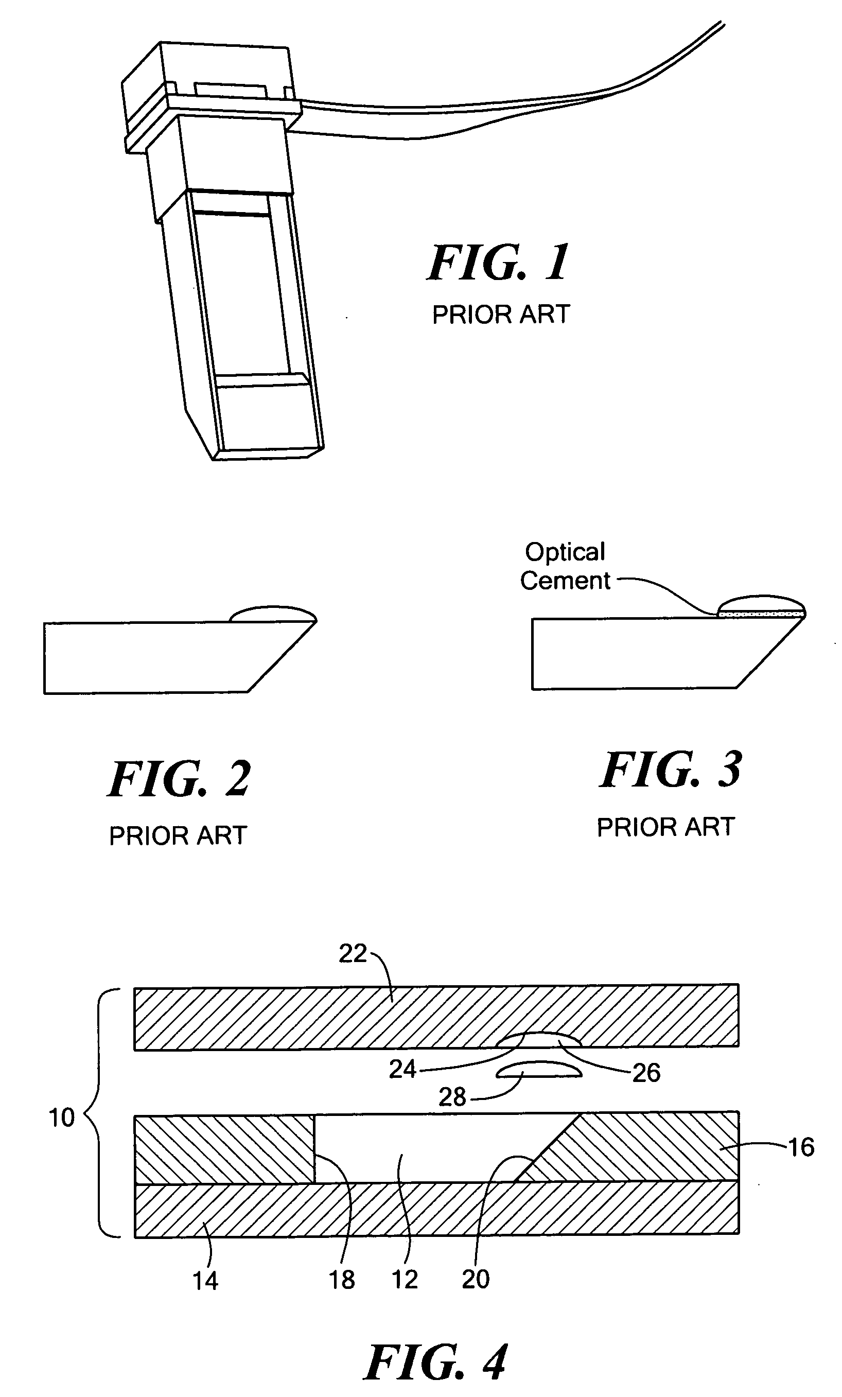
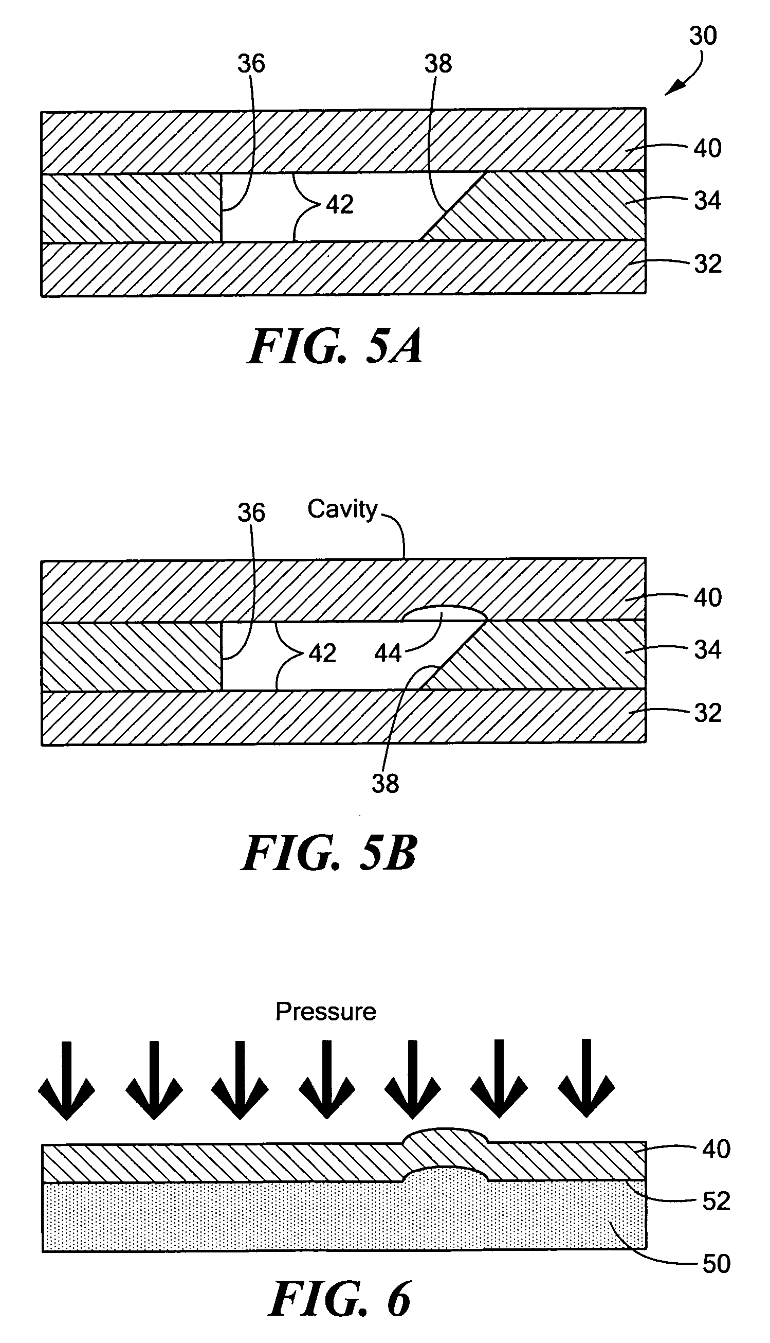
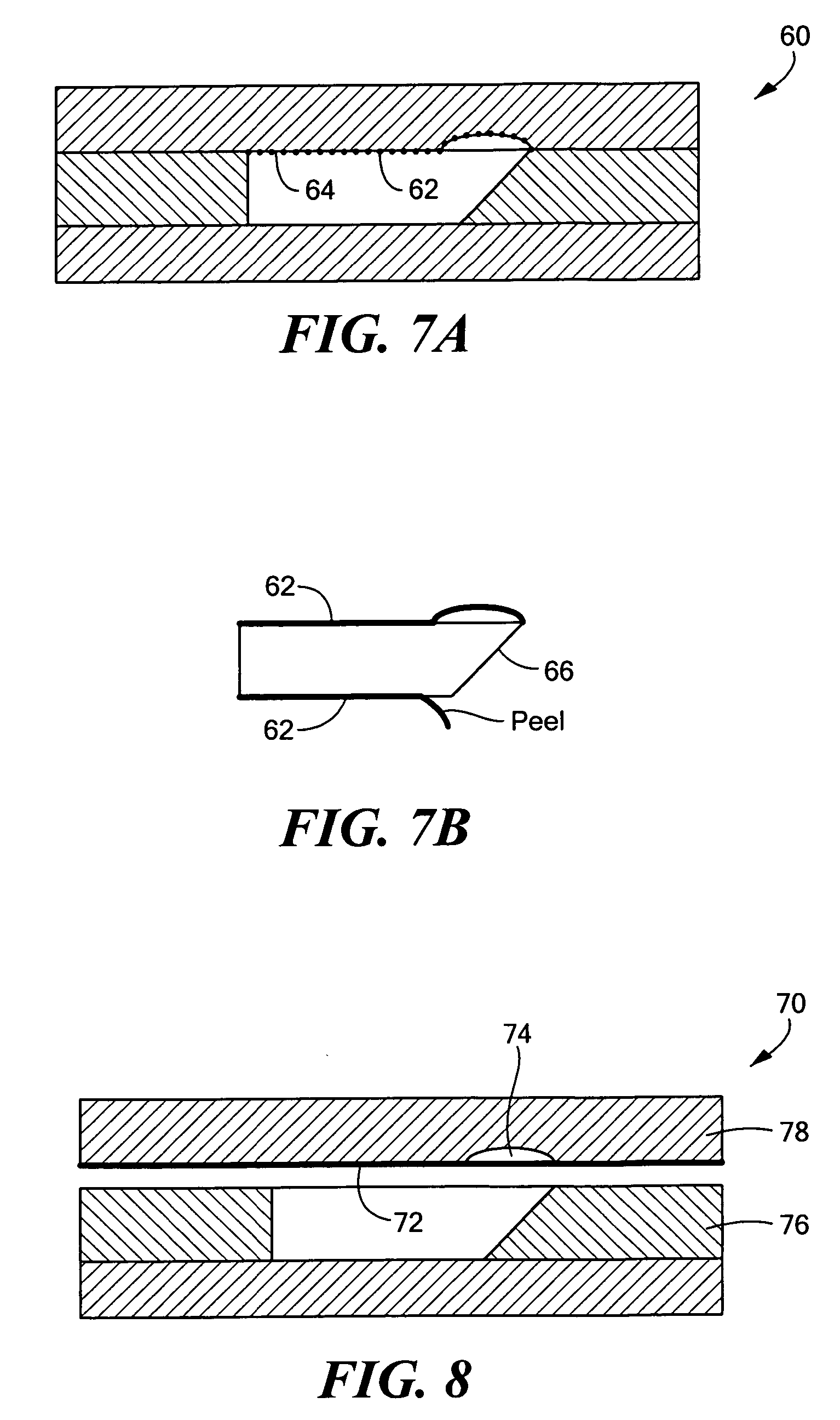
[0028] In the present invention, the difficulties of creating optical systems with protruding lenses on otherwise flat surfaces are overcome. Three method embodiments are presented. The first embodiment has optical elements including lenses, mirrors, etc. incorporated into the mold prior to filling. The second embodiment creates a low use mold from a non-machinable molding plate. The third embodiment incorporates films into the mold. Each embodiment is detailed below.

[0029] In a first embodiment of a method according to the present invention, optical elements are anchored in a mold. Thus, the mold is designed to hold one or more external optical elements such as mirrors or previously produced lenses. The external optical elements may be injection molded, polished, or produced by any other manner known in the art, prior to their placement in the mold and the introduction of a casting medium. The external optical element may, for example, be an injection molded acrylic lens, which ma...


PUM


Abstract

A casting method, rather than injection molding, to produce polymer optical components and systems is provided. The casting process controls shrinkage and stress, thus providing both high bulk uniformity and high quality, accurate surfaces, by incorporating polymer films into the mold. The films may remain incorporated into the part or may optionally be removed from the part after removal from the mold. In addition, the incorporation of separately produced components within the cast part is also provided, eliminating post-casting assembly manufacturing steps.

Description

CROSS REFERENCE TO RELATED APPLICATIONS [0001] This application claims the benefit under 35 U.S.C. § 119(e) of U.S. Provisional Patent Application No. 60 / 656,219, filed on Feb. 25, 2005, the disclosure of which is incorporated by reference herein. [0002] This application is related to U.S. patent application Ser. No. 11 / 065,847, filed on Feb. 25, 2005, the disclosure of which is incorporated by reference herein.STATEMENT REGARDING FEDERALLY SPONSORED RESEARCH OR DEVELOPMENT [0003] N / A BACKGROUND OF THE INVENTION [0004] In the last century, polymers have increasingly been used to fabricate low cost, low weight optics, especially in high volume applications that also have less stringent optical requirements. An additional advantage of plastic elements over the more traditional glass is the ease of fabricating non-spherical (aspheric) surfaces, which can simplify the optical design, reduce the number of required elements, or improve the system performance. The use of plastic in more de...

Claims


Application Information

Patent Timeline
IPC IPC(8): B29D11/00
CPCB29D11/00009B29D11/00
Inventor GILLER, EUGENERENSING, NOA M.ZAVRACKY, PAUL M.
Owner GOOGLE LLC
Why Eureka
Try Eureka