
Aligning polymer films

a polymer film and aligning technology, applied in the field of aligning polymer films, can solve the problems of limiting the process window, requiring many deposition steps using expensive tools, and affecting the process,

Inactive Publication Date: 2009-08-27
GLOBALFOUNDRIES INC
View PDF26 Cites 79 Cited by
  • Summary
  • Abstract
  • Description
  • Claims
  • Application Information

AI Technical Summary

Benefits of technology

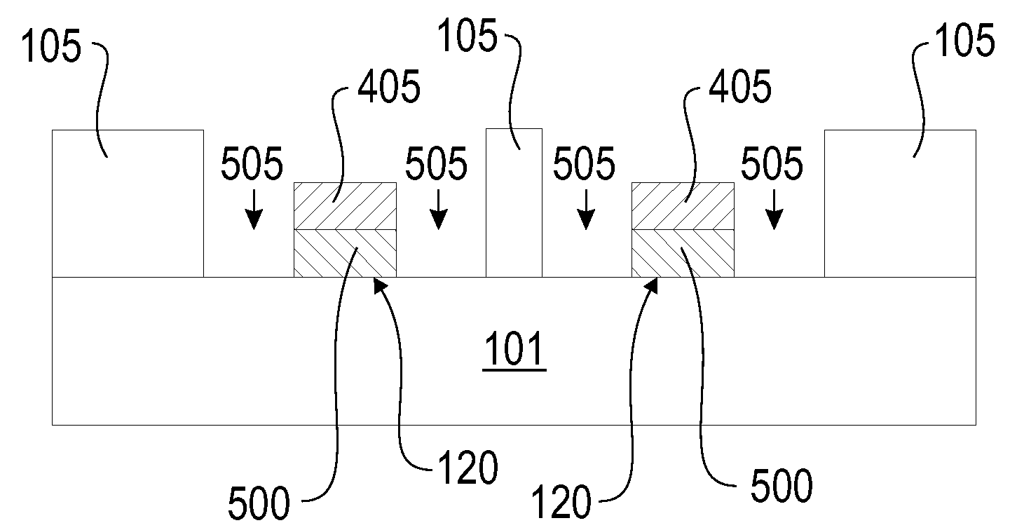
[0014]selectively removing one or more polymers from said segregated film while leaving at least one polymer remaining on said substrate.

Problems solved by technology

However, both these processes have detrimental dependencies on pattern geometry (density and pitch) or resist chemistry which 1) limits the shrink dimension and uniformity in the RELACS process and 2) limits the process window in the SAFIER process.
However these patterning processes require a large number of process steps, frequently require many deposition steps employing expensive tools, and in some cases the dimensions of the resulting structures are dependent upon the coating thickness.

Method used


Image

  • Aligning polymer films
  • Aligning polymer films
  • Aligning polymer films

Examples


example 1

[0070]A solution containing polystyrene (PS, 22 kilograms / more (kg / mole), from polymer source) and polymethylmethacrylate (PMMA, 21 kg / mole from polymer source) and polystyrene-block-polymethylmethacrylate (PS-b-PMMA, 38 kg / mole-36 kg / mole, from polymer source) with a PS:PMMA:PS-b-PMMA weight ratio of 6:3:1 was cast onto a silicon wafer substrate coated with an anti-reflective coating (ARC) with thermally hardened line / space positive photoresist features having a pitch of 240 nm and then baked at 200° C. for 1 minute. PMMA segregated to form lines next to the resist sidewall and PS segregated to the middle of the resist space. PS-b-PMMA resided in the interface between PS and PMMA lines and was used to tune the interfacial energy between PS and PMMA. The sample was etched in an oxygen plasma for 10 seconds to remove the PMMA and showed remaining PS and resist lines with pitch of 120 nm.

example 2

[0071]A polymer blend solution containing polystyrene (PS, 22 kg / mole, from polymer source) and polymethylmethacrylate (PMMA, 21 kg / mole from polymer source) and polystyrene-block-polymethylmethacrylate (PS-b-PMMA, 38 kg / mole-36 kg / mole, from polymer source) with a PS:PMMA:PS-b-PMMA weight ratio of 6:3:1 was cast on a substrate with negative e-beam resist (XR1541, hydrogen silsesquioxane from Dow Corning, hydrophilic resist) line / space features with a pitch of 110 nm and resist space from 50 nm to 80 nm. The sample was baked at 200° C. for 1 minute and etched under oxygen plasma for 10 sec. The remaining PS and resist lines demonstrated successful self-segregation in the narrower resist spaces.

example 3

[0072]A polymer blend solution of poly (α-methyl-(4-hydroxyl benzyl) silsesquioxane-ran-(α-methyl-benzyl silsesquioxane))(poly(HMBS50-r-MBS50)) and poly(1,1,1-trifluoro-2-(trifluoromethyl)-2-hydroxy-pent-4-yl methacrylate) (poly(iPrHFAMA))with weight ratio 1:1 was cast on a substrate with line / space and hole / post features of a standard 193 nm positive resist (AR 1682). The sample was baked at 200° C. for 1 minute, developed in 0.26 N tetramethylammonium hydroxide solution (CD26 developer) for one minute, then rinsed and dried. The poly(iPrHFAMA) was removed by CD26 developer, and poly(HMBS50-r-MBS50) was left forming lines in between the resist lines and forming dots in between resist dots.


PUM

PropertyMeasurementUnit
chemical affinityaaaaaaaaaa
temperatureaaaaaaaaaa
glass transition temperatureaaaaaaaaaa

Abstract

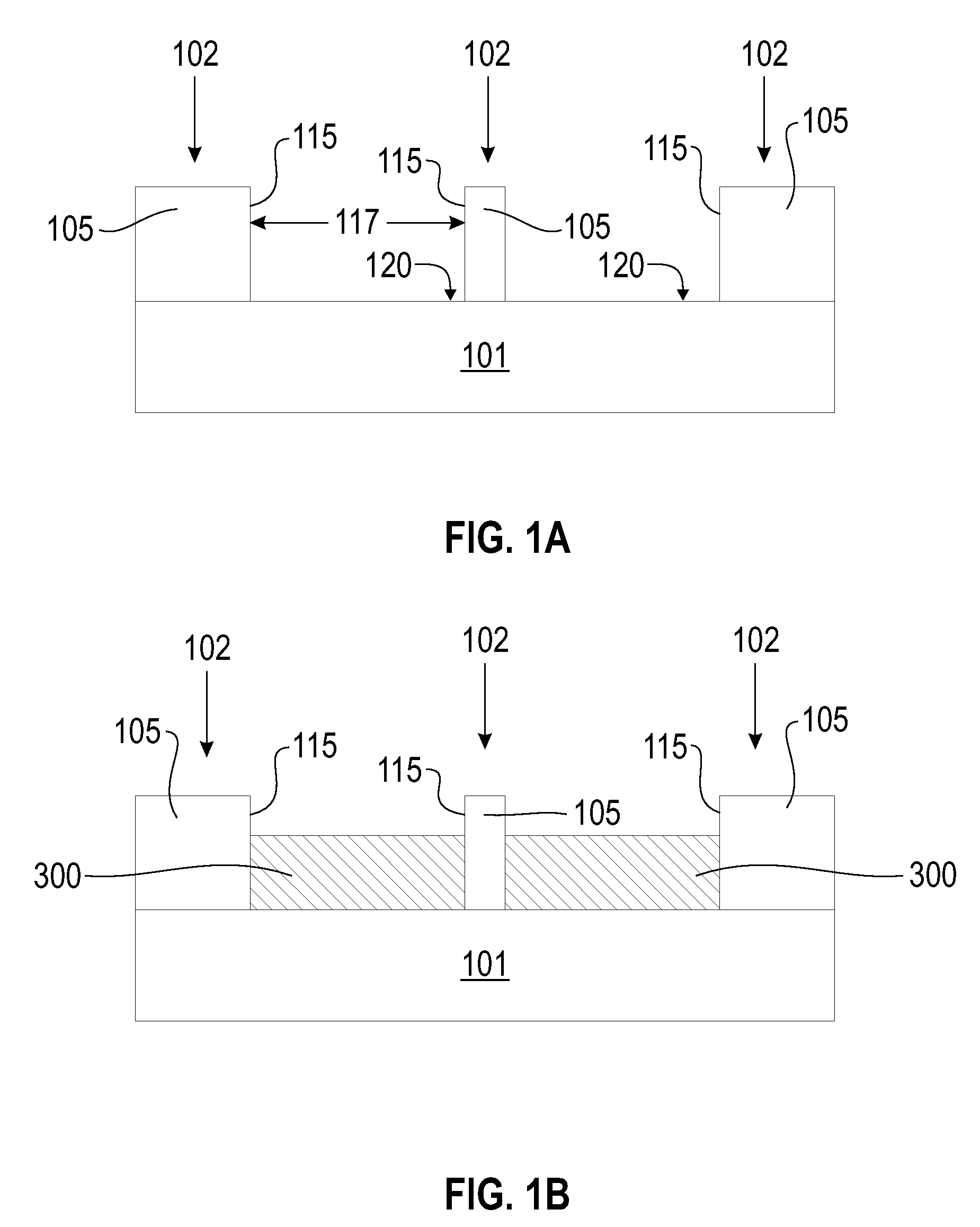
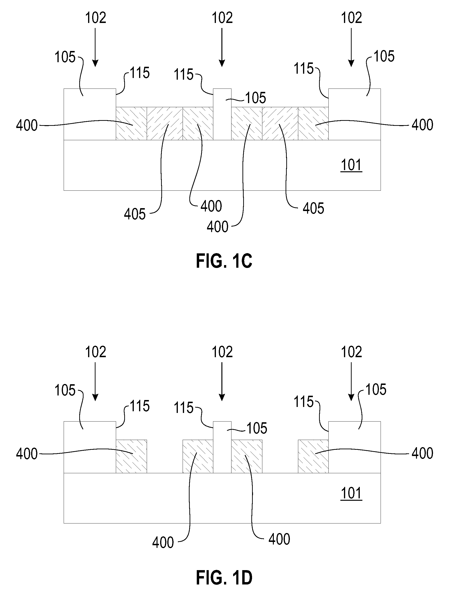
A Method. The method includes forming a substructure, on a substrate, including a feature having a sidewall of a first material and a bottom surface of a second material. Applying a solution including two immiscible polymers and third material to the substructure. The immiscible polymers include a first and second polymer. A selective chemical affinity of the first polymer for the material is greater than a selective chemical affinity of the second polymer for the material. The first polymer is segregated from the second polymer. The first polymer selectively migrates to the at least one sidewall, resulting in the first polymer being disposed between the at least one sidewall and the second polymer. The first polymer is selectively removed. The second polymer remains, resulting in forming structures including the substructure, the third material, and the second polymer. The substructure has a pattern. The pattern is transferred to the substrate.

Description

FIELD OF THE INVENTION[0001]The invention relates to methods for aligning polymers and other materials on substrates and structures formed therefrom.BACKGROUND OF THE INVENTION[0002]Smaller critical dimension (CD) and tighter pitch for both line / space patterns and contact holes allows denser circuitry to be created and therefore reduces overall production cost. For resist space shrink, two widely used processes to reduce the dimensions of patterned features are SAFIER (shrink assist film for enhanced resolution) and RELACS (resolution enhancement lithography assisted by chemical shrink). The SAFIER process decreases the dimensions of the spaces between adjacent resist structures by covering the patterned resist with a layer of polymer which contracts during subsequent heating and stretches the resist structures. The RELACS process uses acid catalyzed cross-linking polymers to form a crosslinked coating around the existing resist features. However, both these processes have detriment...

Claims


Application Information

Patent Timeline
Patent Type & Authority Applications(United States)
IPC IPC(8): B44C1/22
CPCB81B2207/056B81C1/00031Y10T428/24322Y10T428/24802Y10T428/24612H01L21/0337
Inventor CHENG, JOYSANDERS, DANIEL P.SOORIYAKUMARAN, RATNAM
Owner GLOBALFOUNDRIES INC
Learn More