Corrugated flow field plate assembly for a fuel cell

a fuel cell and flow field technology, applied in the direction of fuel cells, fuel cell auxiliaries, electrochemical generators, etc., to achieve the effect of easy formation and low pressure drop operation

Inactive Publication Date: 2002-06-27
BDF IP HLDG
View PDF0 Cites 81 Cited by
  • Summary
  • Abstract
  • Description
  • Claims
  • Application Information

AI Technical Summary

Benefits of technology

0028] Like couplings that are integrally formed into the corrugated plate surface, the coupling subassemblies may be selectively located along each corrugated plate end to create a variety of flow field patterns. The selective nesting of coupling structures may also enable the independent formation of flow field patterns on each surface of the corrugated plate. This flexibility allows a designer to select different preferred flow field patterns for fuel and oxidant flows; for example, a single serpentine flow path may be formed on one side for high pressure drop operation typically desirable for oxidant flow while multiple flow paths may be formed on the other side to provide a lower pressure drop operation typically desirable for fuel flow.
0029] As discussed above, the flow field plate assembly is advantageously relatively simple to manufacture, is readily formable with a variety of different flow field patterns on both sides of the assembly, and tends to be thinner than conventional flow field plates having comparable flow channel dimensions.

Problems solved by technology

This corrugated design tends to result in plates that are thinner than conventional bipolar flow field plates that have flow channels on one surface of the plate that do not overlap in the stack dimension with flow channels on the opposite surface of the plate.

Method used


Image

  • Corrugated flow field plate assembly for a fuel cell
  • Corrugated flow field plate assembly for a fuel cell
  • Corrugated flow field plate assembly for a fuel cell

Examples


Embodiment Construction

)

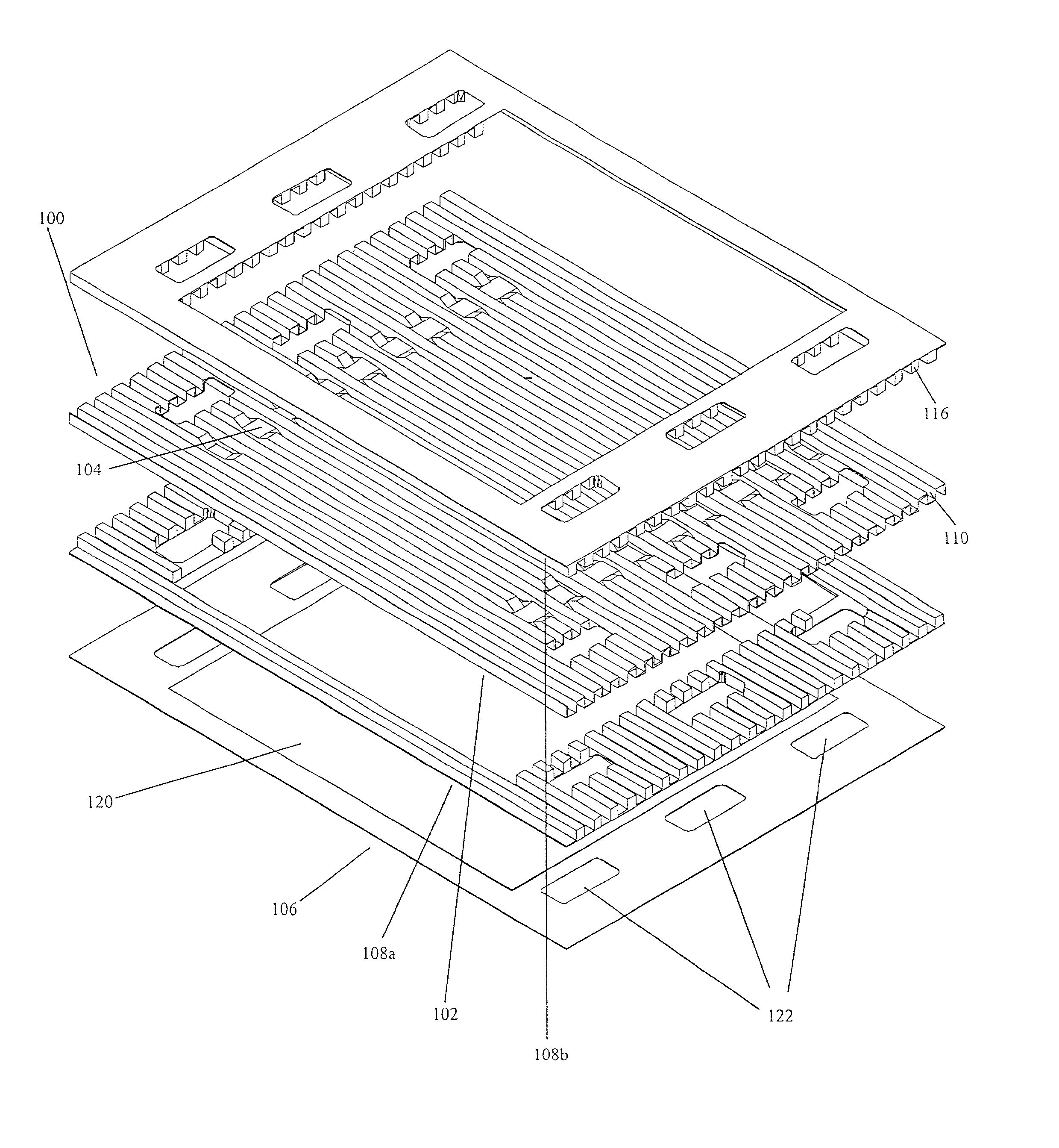
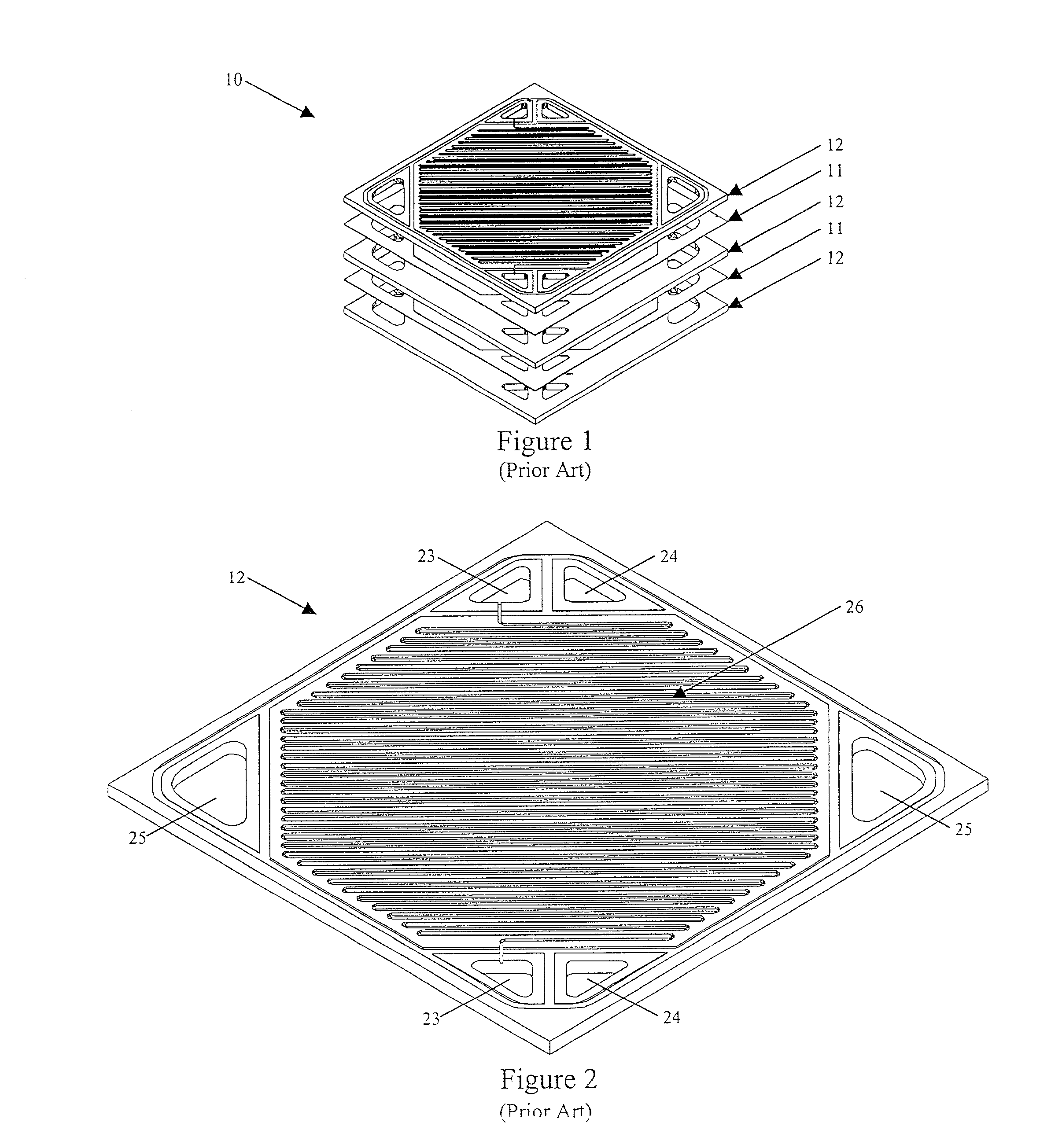
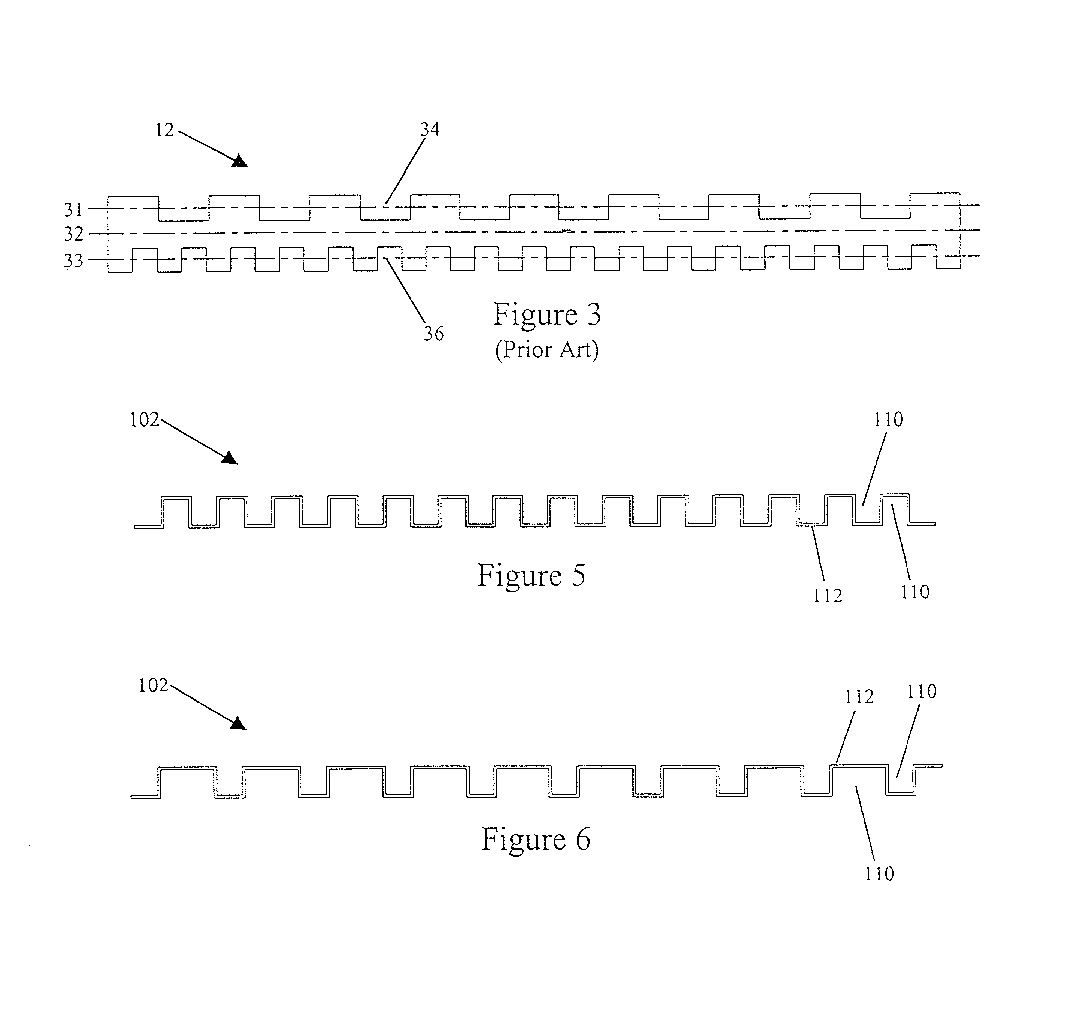
[0044] Referring first to FIGS. 1 and 2, a conventional fuel cell stack 10 comprises multiple membrane electrode assemblies (MEA) 11 separated by bipolar flow field separator plates 12. Flow field plates 12 serve to distribute fuel and oxidant gases to neighboring MEAs as well as to provide a series electrical connection between each MEA. Each plate 12 is typically made of graphite material and has means for distributing reactant gases to a desired side of the plate and for sealing the plate / MEA interface against gas leaks. The plate 12 typically has a plurality of inlet and outlet fuel plenums 23, inlet and outlet oxidant plenums 24, coolant flow plenums 25 (optional), and on each side of the plate, one or more open-faced flow channels 26 that form a flow field pattern for the distribution of one of oxidant or fuel to an adjacent contacting MEA.

[0045] In order to effectively manage water produced as a by-product of the electrochemical reaction, it is desirable for the flow field p...


PUM

PropertyMeasurementUnit
aspect ratioaaaaaaaaaa
thicknessaaaaaaaaaa
depthaaaaaaaaaa

Abstract

Corrugated flow field plates for use in fuel cells typically comprise a plurality of parallel open-faced fluid flow channels for the fuel cell reactants. Complex flow paths, such as serpentine flow paths, may be created in such corrugated flow field plates by incorporating channel couplings within the plate or by attaching coupling subassemblies to the plate. The plates are particularly suitable for use in solid polymer electrolyte fuel cells.

Description

[0001] The present invention relates to fuel cells and particularly to solid polymer electrolyte fuel cells incorporating a proton exchange membrane. More particularly, the present invention relates to a corrugated flow field plate assembly for a fuel cell and a means for interconnecting fluid flow channels therein.[0002] Electrochemical fuel cells convert fuel and oxidant to electricity and reaction product. In electrochemical fuel cells employing hydrogen as the fuel and oxygen as the oxidant, the reaction product is water. Conventional proton exchange membrane ("PEM") fuel cells generally employ a planar, layered structure known as a membrane electrode assembly ("MEA"), comprising a solid polymer electrolyte or ion exchange membrane, which is neither electrically conductive nor porous, disposed between an anode electrode layer and a cathode electrode layer. The electrode layers are typically comprised of porous, electrically conductive sheets with electrocatalyst particles at eac...

Claims


Application Information

Patent Timeline
Patent Type & Authority Applications(United States)
IPC IPC(8): H01M8/02H01M8/24
CPCH01M8/0254H01M8/0258Y02E60/50H01M8/0263H01M8/241H01M8/026H01M8/0267H01M8/242H01M8/2483H01M8/0273
Inventor MCLEAN, GERARD F.DJILALI, NEDJIBREID, CHRISTOPHER E.J.LINDSTROM, JEREMYDONIS, WALTER ROBERTO MERIDA
Owner BDF IP HLDG
Why Eureka
Try Eureka