Electrical impedance method and apparatus for detecting and diagnosing diseases

a technology of electric impedance and diagnostic equipment, applied in the direction of calibration equipment, sensors, coupling device connections, etc., can solve the problems of reducing image fidelity and resolution, complex mathematical methods for constructing impedance images

Inactive Publication Date: 2002-09-05
IMPEDIMED
View PDF0 Cites 68 Cited by
  • Summary
  • Abstract
  • Description
  • Claims
  • Application Information

AI Technical Summary

Benefits of technology

[0012] The methodology of the present invention is implemented by a data acquisition and analysis apparatus that was developed for the special requirements of the invention. An improved breast electrode array is also provided of a design and construction that allows excellent conformability of the array to a breast surface and precise positioning of electrodes. This ensures that the multiplicity of positions that impedance measurements are obtained from in a first body part correspond as precisely as possible to the multiplicity of positions that measurements are obtained from in another, homologous, second body part. The apparatus has a number of innovations that provide rapid, accurate impedance measurements from a large number of electrode combinations, and virtually immediate data analysis and display. Impedance data are obtained in organized patterns from two anatomically homologous body regions, one of which may be affected by disease.
[0014] In another embodiment of the invention, the differences between corresponding impedance readings in the two body parts are compared in variety of ways that allow the calculation of metrics that can serve either as an indicator of the presence of disease or localize the disease to a specific breast quadrant or sector. Impedance differences are also displayed in a circular pixel plot in a representation of the frontal plane of the breast in this disclosure, although other shape plots in the same or other planes could effectively be produced with suitable choice of electrode geometry and positioning. The use of impedance differences subtracts out a voluminous and complex amount of impedance data produced by irregular, three-dimensional current paths, since under generally normal circumstances, the paths can be expected to be substantially identical in both body parts. Remaining differences are assumed to be due to disease states, and are much more manageable analytically.
[0036] Moreover, a method of minimizing the number of connections in a conductive path of the electrode array and the connector is disclosed. The method comprises:

Problems solved by technology

However, there are basic problems when trying to construct an image from impedance data.
As a result, the mathematics for constructing the impedance image is very complex and requires simplifying assumptions that greatly decrease image fidelity and resolution.

Method used


Image

  • Electrical impedance method and apparatus for detecting and diagnosing diseases
  • Electrical impedance method and apparatus for detecting and diagnosing diseases
  • Electrical impedance method and apparatus for detecting and diagnosing diseases

Examples


Embodiment Construction

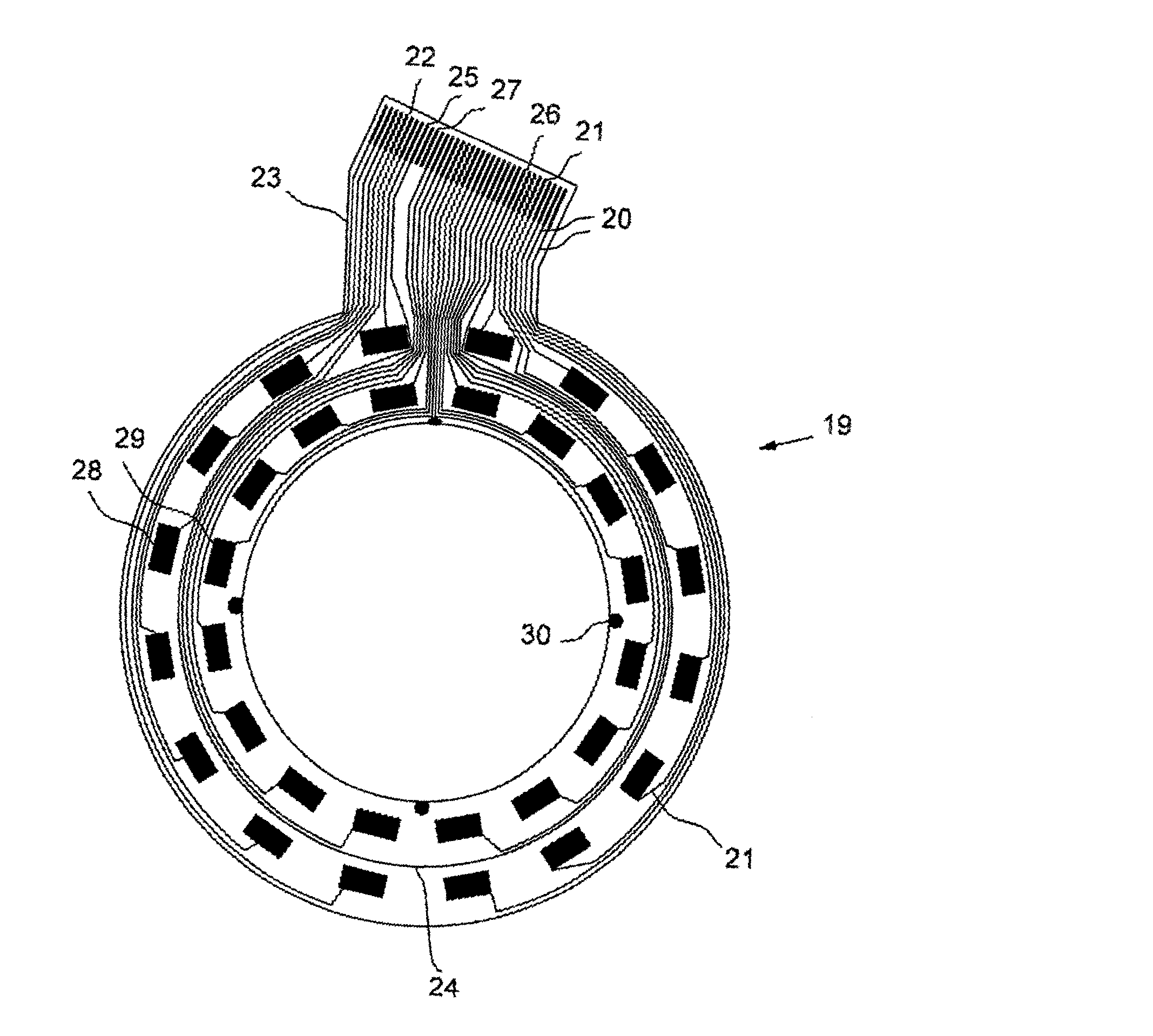
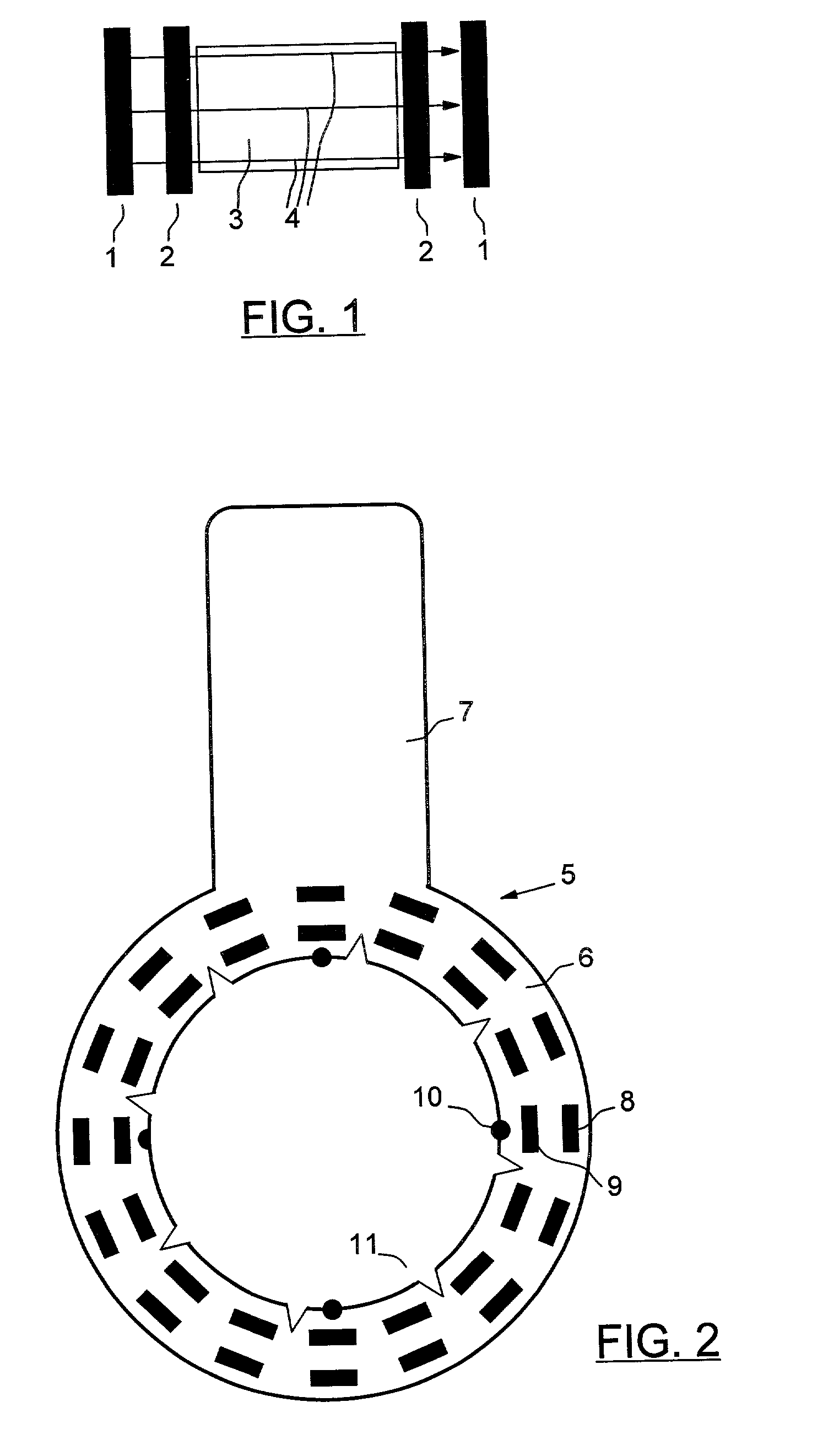
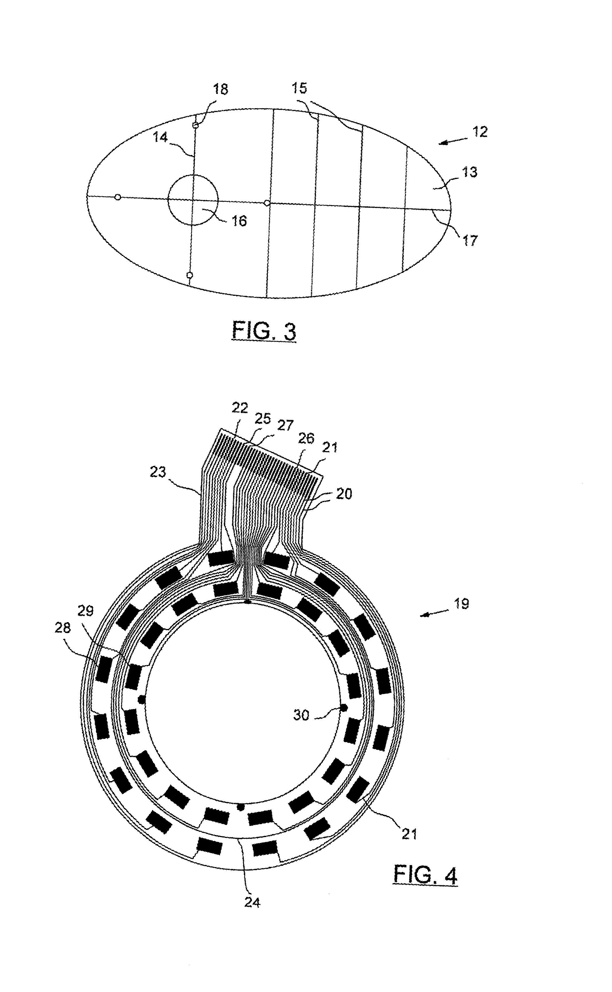
[0128] Electrical Impedance and the Four Electrode Measurement Technique

[0129] Electrical impedance is measured by using four electrodes as shown in FIG. 1. The outer pair of electrodes 1 is used for the application of current 1, and the inner pair of electrodes 2 is used to measure the voltage V that is produced across a material, such as tissue 3, by the current. The current 1 flowing between electrodes 1 is indicated by the arrows 4. The impedance Z is the ratio of V to I; i.e., 1 Z = V I .

[0130] By using separate electrode pairs for current injection and voltage measurement polarization effects at the voltage measurement electrodes are minimized and a more accurate measurement of impedance can be produced.

[0131] Impedance consists of two components, resistance and capacitive reactance (or equivalently, the magnitude of impedance and its phase angle). Both components are measured, displayed, and analyzed in the present invention. However, for the purpose of explanation of the inv...


PUM


Abstract

The present invention relates to an improved method and apparatus for detecting and diagnosing disease states in a living organism by using a plurality of electrical impedance measurements. In particular, the invention provides for an improved electrode array for diagnosing the presence of a disease state in the human breast, and discloses a method of application of the array to the breast that ensures that the multiplicity of impedance measurements obtained from a first body part correspond as precisely and reproducibly as possible to the multiplicity of impedance measurements that are obtained from another, homologous, second body part. A number of diagnostic methods based on homologous electrical difference analysis are disclosed, including the calculation of a number of metrics used to indicate disease states by comparison with pre-established threshold values, and the construction of a number of graphical displays for indicating the location of disease to a body part sector.

Description

[0001] The present invention relates to an improved method and apparatus for detecting and diagnosing disease states in a living organism by using a plurality of electrical impedance measurements.[0002] Methods for screening and diagnosing diseased states within the body are based on sensing a physical characteristic or physiological attribute of body tissue, and then distinguishing normal from abnormal states from changes in the characteristic or attribute. For example, X-ray techniques measure tissue physical density, ultrasound measures acoustic density, and thermal sensing techniques measures differences in tissue heat. Another measurable property of tissue is its electrical impedance; i.e., the resistance tissue offers to the flow of electrical current through it. Values of electrical impedance of various body tissues are well known through studies on intact humans or from excised tissue made available following therapeutic surgical procedures. In addition, it is well documente...

Claims


Application Information

Patent Timeline
Patent Type & Authority Applications(United States)
IPC IPC(8): A61B5/296
CPCA61B5/04085A61B5/0536A61B2562/0209A61B2562/046A61B5/282
Inventor ORGAN, LESLIE W.SMITH, KENNETH C.SAFAEE-RAD, REZAGRAOVAC, MILANDARMOS, GEORGE P.GAVRILOV, ILYA
Owner IMPEDIMED
Why Eureka
Try Eureka