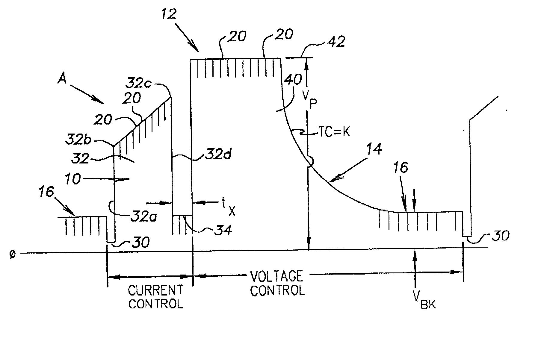
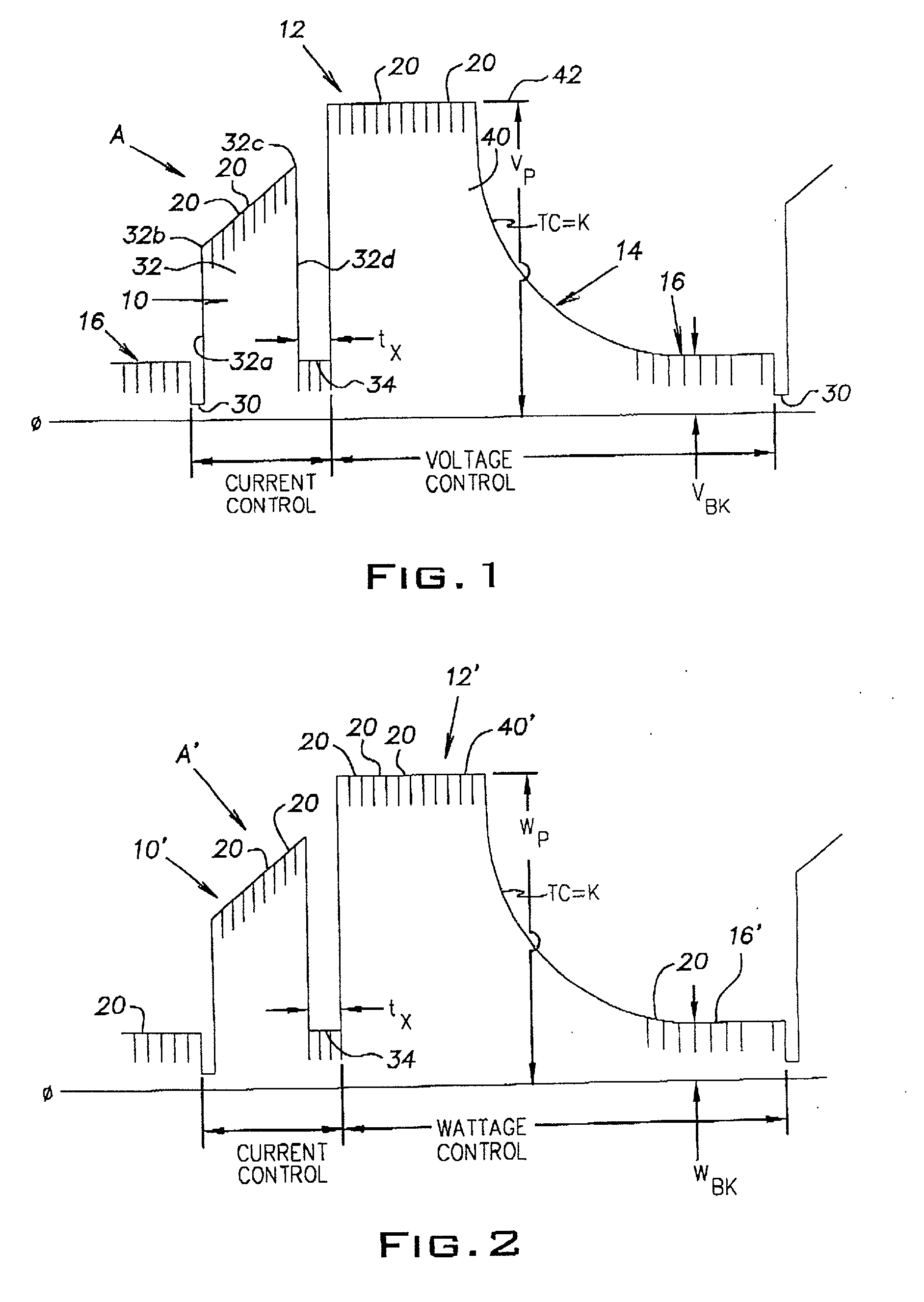
[0020] Referring now to the drawings wherein the showings are for the purpose of illustrating a preferred embodiment of the invention only, FIG. 1 shows an STT type waveform A for a short circuit welding process including a short condition 10, an arc condition 12, tailout 14 and background 16. This waveform is the current profile through the weld and is formed by a plurality of current pulses 20 created at a frequency exceeding 18 kHz. The widths of the current pulses control the magnitude or height of the waveform as illustrated in FIG. 1. Short circuit welding includes alternating between an arc or plasma condition and a short condition initiated at the time a molten metal ball on the end of an electrode contacts the workpiece. This event occurs at time 30. Metal is then transferred from the electrode to the workpiece by surface tension action. This action is accelerated by pinch pulse 32 used to control the current with a profile having a rapidly increasing current section 32a, a break point 32b to give a second slope, and a premonition point 32c. As will be explained later, a dv/dt, dr/dt or dp/dt circuit detects when the surface tension transfer of molten metal is ready to separate or explode. At that time, the voltage increases because the cross section decreases rapidly. This event anticipates the explosion or separation of the molten electrode tip from the workpiece. To reduce spatter, the waveform includes a current plunge section 32d before actual metal separation. Current pinch pulse 32 is controlled in the STT technology by the shape of pinch pulse 32 shown in FIG. 1. Thereafter, there is a slight delay 34 indicated to be time t.sub.x before the current rapidly increases to create plasma boost pulse 40. In the STT technology, this rapid increase in current is toward a fixed peak current. In the present invention, the controller shifts the power supply between current control during the short condition and to voltage control during the arc condition 12. This causes a current increase in the plasma boost pulse 40 toward a peak 42 of a voltage function. In the preferred embodiment, peak 42 is a peak voltage that is held constant. Such constant voltage normally produces a generally constant current as shown in FIG. 1. After the desired amount of energy has been transmitted to create a molten metal ball, the voltage of the power supply transitions along time constant curve or tailout 14 where the time constant CT is equal to K. This curve, or tailout, transitions to a background voltage level 16. In the present invention, the waveform implemented during arc condition 12 is a voltage waveform having a peak voltage V.sub.P and a background voltage V.sub.BK. At the end of the background current there is a new short at time 30 causing the voltage to plunge and shift the power supply to a current control for the pinch pulse 32. Thus, the invention involves using current control during the short condition 10 and voltage control during arc position 12. In each instance, these controls follow predetermined waveforms to produce the desired characteristics. Consequently, the arc condition 12 is a voltage function. In the preferred embodiment, the voltage function is the voltage across the arc. As will be explained later, a standard closed loop control operated during the short condition to create a desired presized, preselected waveform during condition 10. The same concept, i.e. current control during the short condition and voltage function control during condition 12', is used in the second embodiment of the invention illustrated in FIG. 2. Waveform A' includes a short condition 10' and an arc condition 12'. The voltage function used during condition 12' for closed loop control is wattage. The plasma boost pulse 40' and background 16' are peak wattage W.sub.P and background wattage W.sub.BK, respectively. The voltage function is sometimes joules, so a joules closed loop feedback produces a waveform as shown in FIGS. 1 and 2.
[0021] Utilizing a pulse width modulated, inverter based power supply of the type used in the preferred embodiment of the present invention results in the current and voltage curves schematically illustrated in FIG. 3. Current curve 100 plunges at time 102 when the molten metal ball is shorted to the workpiece causing the voltage to plunge. Such voltage decrease is to a level less than a reference voltage V.sub.R causing the power supply to shift from voltage control to current control. Current control implements the short portion of the weld cycle. The current is held down for a short time until time 104. Current control of the power supply is then released allowing a rapid increase in the current to create pinch pulse 110 having a break point 110a and a premonition point 110b. As previously explained, the current control of the power supply plunges the current as indicated by portion 110c. Thus, the explosion or metal separation occurs at the low current 106 that is maintained for a time t.sub.a. During this time, the current mode of operation allows an increase in voltage to create current pulse 120 which current is dictated by the predesigned voltage control waveform. Current pulse 120 has a steep, leading edge 122 during which the voltage is at the desired level while the current is advancing toward the upper peak current 124. This current level is caused by the set peak voltage used during voltage control of the power supply. Thereafter, current pulse 120 transitions into background portion of the arc condition along gradual curve 126. Pulse 120 is a current pulse with a shape dictated by the desired voltage waveform shown in the right portion of the voltage curve at the bottom portion of FIG. 3. Current control defines pulse 110 and voltage control defines pulse 120. At point 152, the voltage control experiences a short circuit and control is shifted from voltage to current. Thereafter, a low current is maintained until time 104. Current pulse 110 is then created by the desired current waveform. This control dictates the voltage variations that follows curve 160. The power supply maintains the desired shape of pinch pulse 110. Voltage immediately rises along portion 160a as a result of the desired current. At break point 110a, the voltage transitions along curve 160b until portion 160c where the voltage is plunged in response to the premonition signal. This is still in the current control mode. The shorted electrode separates at time 170, causing the voltage to increase to a level above reference V.sub.R causing the power supply to shift to a voltage control waveform level 172 as the arc voltage obtained when arc is reestablished at low current 106. This next waveform includes the peak voltage 174. To reach the peak voltage, there is a time T.sub.b. Time T.sub.a plus time T.sub.b equals the previously discussed delay 34 having a time T.sub.x. After processing of the voltage waveform to melt the electrode, the voltage transitions along portion 176 to the background voltage 178 where the voltage is held awaiting the next short circuit. In practice, 100 to 300 cycles of pulses shown in FIG. 3 are performed each second. By adjusting the peak voltage and/or background voltage during the arc or plasma condition of the cycle, the temperature and/or fluidity of the weld puddle is controlled.
[0022] In practicing the invention, the preferred embodiment employs a digital control scheme illustrated in block diagram and logic chart 4 wherein welder 200 has a logic processor based controller C programmable to implement a short circuit arc welding process, such as an STT short circuit welding process. Inverter 202 has a standard rectified output circuit 204 for directing current through switch 206 and inductor 208 to electrode 210 in the form of an advancing wire used to weld workpiece 214. Voltage feedback 220 directs the level of the arc voltage back to digital controller C. In a like manner, shunt 222 directs the instantaneous arc current back to controller C by feedback line 224. In accordance with standard control technology, the logic processor in controller C includes a digitally implemented pulse width modulator 230 having an input digitized error amplifier 232 with a waveform control represented by line 240. Pulse width modulator 230 causes inverter 202 to follow the waveform on line 240 based upon the feedback value in line 242. In accordance with standard practice, a current waveform generator 250 is provided to give the desired profile of the current pulse between the electrode and workpiece during various portions of the weld cycle. In this invention, the current waveform generator 250 is used by pulse modulator 230 for only a portion of the time or segment of the weld cycle as determined by the conductive state of digital enable switch 252. When the switch is enabled, generator 250 controls the logic on line 240 so that the feedback level on line 242 follows the desired precise current profile. In accordance with the invention, a voltage waveform generator 260 is also provided. Generator 260 has an output directed through digital enable switch 262 to input 240. Switch 252 and switch 262 are anti-coincident. When one enable switch is closed, the other enable switch is opened. Thus, error amplifier 234 receives a waveform generated from either the current waveform generator 250 or the voltage waveform generator 260 according to the conductive condition of switch 252, 262. In accordance with standard technology, a premonition circuit 270, indicated as a dv/dt circuit, creates a logic in line 272 for opening switch 206 when the metal transfer is near the breaking point. Resistor 274 is then inserted into the weld circuit to reduce current along portion 110c. To shift between the current mode and voltage mode, a digitized comparator 280 has a positive input 282 connected with the voltage feedback 220 and a negative input 284 controlled by reference voltage V.sub.R. Output line 290 of comparator 280 is connected to a voltage mold digital switch 292. The logic on line 290 is inverted by inverter 294 to provide the opposite logic on line 296 for controlling current mode switch 298. In operation, when the voltage decreases on line 222 at the start of a short, a logic zero appears in line 290. This deactivates switch 292 and switch 262. Inverter 294 produces a logic 1 in line 296. This activates switch 298 so the current feedback level in line 224 is directed to input 242 of error amplifier 234. At the same time, the logic 1 on line 296 enables digital switch 252 so waveform generator 250 is connected to input 240 of the error amplifier. During this operation, the inverter 220 follows waveform 100 from generator 250. At the end of the short, voltage shifts up on line 170 shown in FIG. 3. Then, the value on input 282 exceeds the reference voltage on line 284. A logic 1 is created in line 290 for closing voltage mode switch 292 and enabling switch 262 so generator 260 controls the logic on line 240. At this same time, switches 252 and 298 are deactivated. The feedback voltage signal on line 220 is directed through switch 292 to input 242. In this manner, inverter 202 follows waveform 150 of voltage waveform generator 260. This generator could also be a wattage waveform generator or a joules waveform generator. All of these iterations have been practiced to control the arc condition of the short circuit welding process. For setup, rheostat 300 adjusts the peak voltage or the peak wattage in the waveform of generator 260. In a like manner, rheostat 302 control the time constant for the tailout and rheostat 304 controls the background voltage or wattage for the waveform from generator 260. The logic scheme disclosed in FIG. 4 is processed by digital technology in controller C and a variety of digital techniques can be used to accomplish the objective of generally operating the arc condition by a waveform tracking the desired function of voltage. In the past, the waveform during the arc condition has been merely an extension of the short circuit waveform so that the advantage of controlling the arc as a voltage function was not available.
[0023] In some situations, after the molten ball has been formed, it is desirable to shift to current control during the arc condition. A digital switch is employed where the logic processor opens line 290 by a switch 290a illustrated in FIG. 4A. This two pole switch concept grounds line 290b by ground 290c. This places a logic zero on line 290b to shift the switches to current control. This switch action is selected by the logic processor and is after the molten ball is formed by the plasma boost pulse.
[0024] FIGS. 5 and 6 illustrate slight modifications of the block diagram and logic chart of FIG. 4. In FIG. 5, the voltage function is wattage; therefore, the inputs of line 282 of comparator 280 is the product of the voltage feedback on line 220 and current feedback on line 224. These values are combined by the multiplier 210 to produce a value in line 312 representing the wattage feedback. The current feedback 224 is used at the input of switch 298 as previously shown in FIG. 4. By using the slight modification shown in FIG. 5 for the digital processing in controller C, the arc condition is controlled by a wattage feedback while the short condition is controlled as shown in FIG. 4 by a current feedback. In FIG. 6, the product in line 312 is integrated by integrator 320 to produce a joules feedback in line 322. This is directed to the positive input 282 of comparator 280 and to the input of switch 292 so the arc condition is controlled by a waveform that is a precise reflection of the desired joules. Other such changes in the digital processing schematically illustrated in FIG. 4 can be used so long as the pulse portion of the arc condition is controlled by a waveform that is a precise representation of a voltage function. The voltage rating of the power supply will not be exceeded by anomalies in the welding process.