Method using an optical signal for detecting overheating and fire conditions in an aircraft

an optical signal and aircraft technology, applied in the direction of optical radiation measurement, fire alarm radiation actuation, instruments, etc., can solve the problems of reducing the precision affecting the accuracy of the sensor operation, and requiring a rather complicated and costly manufacturing process for sensors

Inactive Publication Date: 2002-09-12
AIRBUS OPERATIONS GMBH
View PDF17 Cites 46 Cited by
  • Summary
  • Abstract
  • Description
  • Claims
  • Application Information

AI Technical Summary

Benefits of technology

[0013] The invention makes advantageous use of the Rayleigh effect, whereby a temperature increase will cause the optical fiber or the fiber optic cable to exhibit a different refraction characteristic at the affected location. Also, the Fresnel effect, by which a reflection pulse will be generated, is further advantageously used. Thus, in connection with the Rayleigh effect the invention can measure a temperature increase that arises at a certain location along the fiber optic cable, and in connection with the Fresnel effect, the invention can precisely determine the location of this temperature increase relative to the total length of the fiber optic cable. Alternatively, the location of the overheating condition can be determined with respect to an absolute distance of the location from one end of the cable.
[0016] The inventive method further can determine the duration of an overheating condition at any respective location, and can determine the temperature progression over prescribed time intervals at each respective location, by simply repeating successive cycles of the monitoring process. This enables better diagnosis of problems, and allows temporary, short-duration and thus non-critical overheating conditions to be indicated or the like, without triggering a drastic corrective measure such as shutting down the affected system or component.

Problems solved by technology

In the event of a rupture or leak of this pipe system, the hot pressurized air flows out of the pipe system and can damage other components or systems of the aircraft arranged near the location of the pipe rupture or leak.
The sensors require a rather complicated and costly manufacturing process, and also require a defined selection and setting of the desired trigger temperature during the manufacturing process.
The tolerance range for the so-called trigger point or trigger temperature is relatively large, which diminishes the precision of the operation of the sensor.
The ability to localize the area of the overheating condition using the conventional sensors in the conventional system is relatively inexact.
Furthermore, the measurement signal given off by the sensor and received and evaluated by the computer must be shielded, because it is sensitive to electromagnetic interferences.
Furthermore, any faulty interruption of the fiber optic cable can be detected, due to the change of the end reflection signal.

Method used


Image

  • Method using an optical signal for detecting overheating and fire conditions in an aircraft
  • Method using an optical signal for detecting overheating and fire conditions in an aircraft

Examples


Embodiment Construction

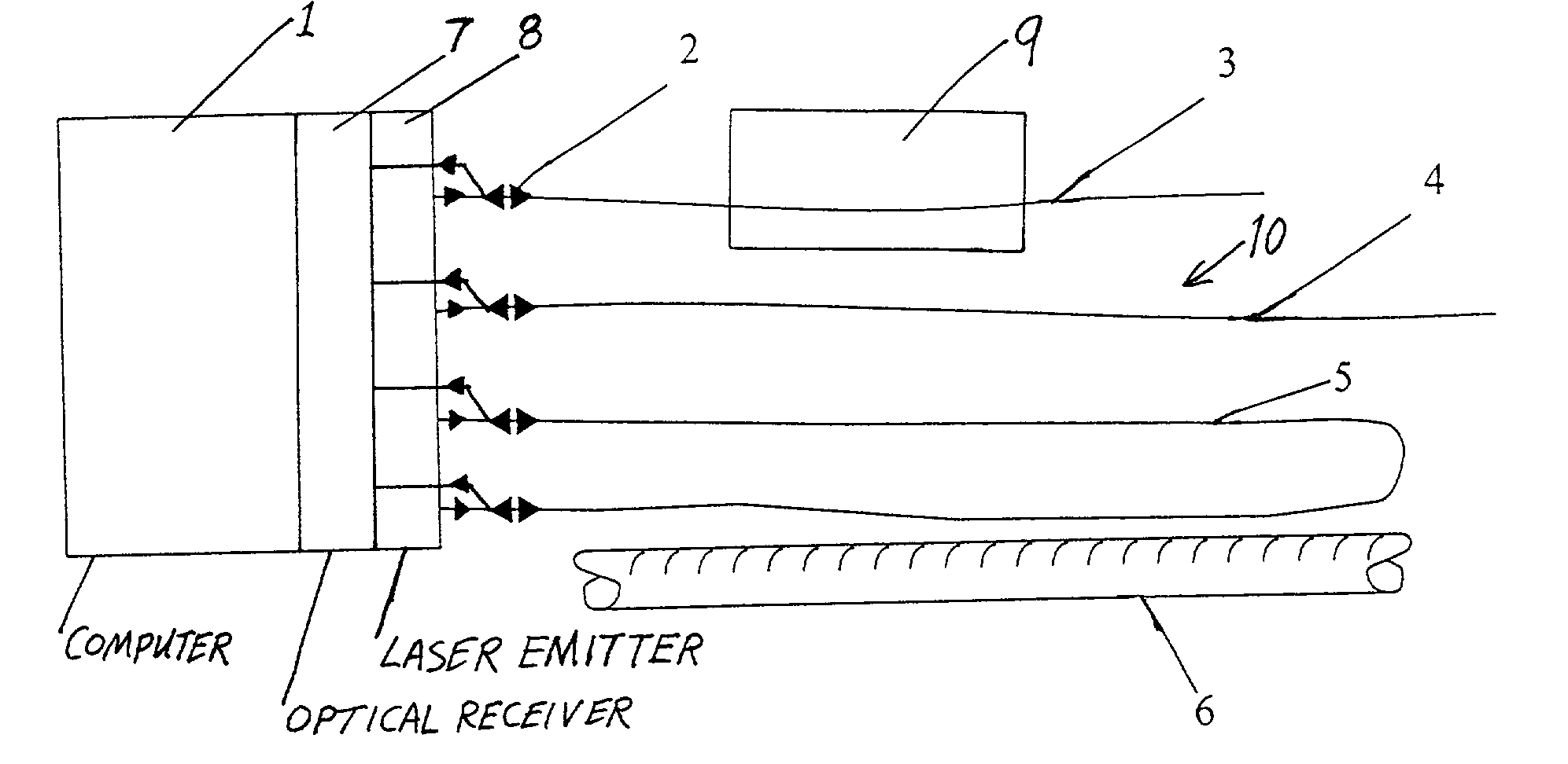
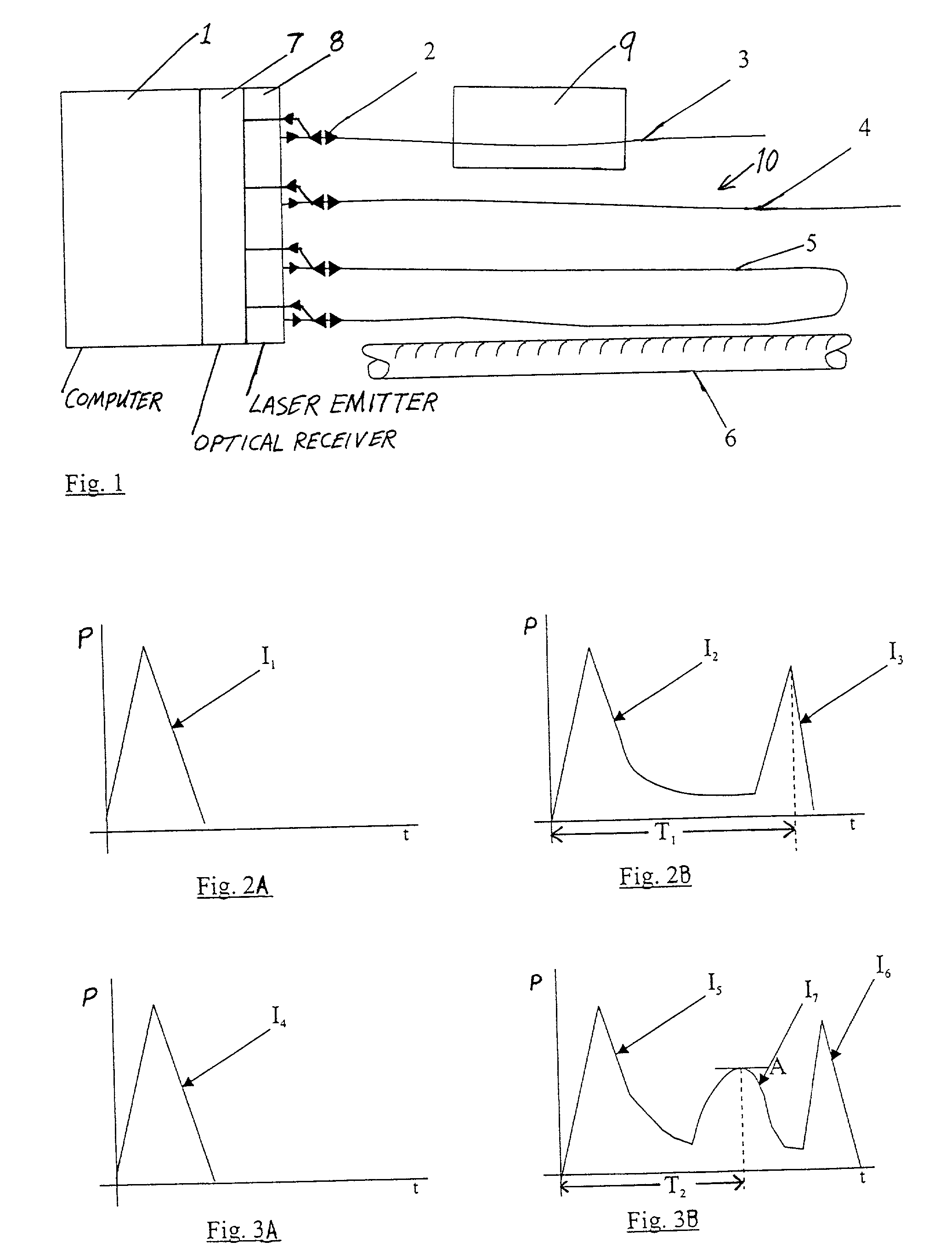
[0025] FIG. 1 schematically shows a general overview of a monitoring arrangement and sensors connected thereto for monitoring the temperature of a monitored area so as to detect an overheating or fire condition in the monitored area. The general term "overheating condition" includes a fire condition. The monitoring arrangement includes a computer 1 connected to an optical receiver and a laser source or emitter 8. The sensors include three representative sensors 3, 4 and 5 that are each connected via an interface 2 to the optical receiver 7 and the laser emitter 8, such that the laser emitter 8 can selectively feed a laser pulse through the respective interface 2 into the respective sensor 3, 4 and 5, and so that the optical receiver 7 can receive return or reflection pulse from the respective sensor 3, 4 or through the associated interface 2. The laser emitter 8 is connected to the computer 1 to be controlled and selectively actuated by the computer 1. The optical receiver 7 is conn...


PUM

PropertyMeasurementUnit
temperaturesaaaaaaaaaa
temperatureaaaaaaaaaa
reflectionaaaaaaaaaa

Abstract

A fiber optic cable forms a temperature sensor arranged along an object or space to monitor the temperature thereof and detect overheating or fire conditions. An end of the sensor is con5 nected through an interface to a laser emitter and an optical receiver, which are further connected to a computer. The computer controls the laser emitter to emit a laser pulse into the sensor. The optical receiver receives the resulting reflection signal from the sensor, and provides a corresponding signal to the computer to be evaluated in connection with a nominal comparison signal. If any location of the sensor is subjected to an unacceptable temperature increase, the sensor's refractive characteristics are changed, to cause an additional reflection pulse in the reflection signal. By evaluating the amplitude and the return time of the additional reflection pulse, the temperature level and the location of the overheating condition are determined by the computer.

Description

PRIORITY CLAIM[0001] This application is based on and claims the priority under 35 U.S.C. .sctn.119 of German Patent Application 101 11 640.3, filed on Mar. 10, 2001, the entire disclosure of which is incorporated herein by reference.[0002] The invention relates to a method for detecting and signaling the existence of overheating conditions and fires in an aircraft, and especially for detecting and identifying the location of an unacceptable temperature increase in a space, in a pipe or conduit, on a device, or in a pressurized or compressed air system, for example the bleed air system of which the pipes or conduits are connected to the aircraft engines for tapping hot pressurized bleed air therefrom. The temperature increase or unacceptable elevated temperature condition and its spatial location are detected by means of a sensor and the corresponding sensor signal is provided to an evaluating unit for evaluation and preferably for the generation of an alarm process and / or system sw...

Claims


Application Information

Patent Timeline
Patent Type & Authority Applications(United States)
IPC IPC(8): A62C3/08A62C37/00B64D45/00F16D7/00F16P7/02G01J1/04G01J5/08G01K11/00G01K11/32G08B17/12G08B21/00G08B25/04
CPCB64D45/00B64D2045/009G01K3/005G01K11/32G08B17/06
Inventor DAMMANN, HANS-JOACHIM
Owner AIRBUS OPERATIONS GMBH
Why Eureka
Try Eureka