Magnetron with diamond coated cathode

a diamond coated cathode and magnetic field technology, applied in the direction of electric variable regulation, process and machine control, instruments, etc., can solve the problems of affecting the operation of the device. , to achieve the effect of reducing the cost of operation, minimizing electronic noise, and increasing the operating li

Inactive Publication Date: 2002-09-12
TERAPHYSICS CORP
View PDF0 Cites 10 Cited by
  • Summary
  • Abstract
  • Description
  • Claims
  • Application Information

AI Technical Summary

Benefits of technology

0015] One advantage of the present invention is the provision of a magnetron device capable of sustaining operation without an external source for producing primary electrons, such as heat source, thereby significantly reducing the cost of operation.
0016] Another advantage of the present invention is the provision of a magnetron device having a well defined electron emission which minimizes electronic noise.
0017] Another advantage of the present invention is the provision of a magnetron device having an increased operating life.
0018] Another advantage of the present invention is the provision of a magnetron device which eliminates warm-up delays.
0019] Another advantage of the present invention is the provision of a magnetron device which minimizes the need for ancillary equipment.
0020] Yet another advantage of the present invention is the provision of a magnetron device capable of emitting electrons upon application of a relatively low level of voltage.

Problems solved by technology

However, secondary electrons only make up approximately 60% of the overall electron emission in known magnetron devices.
First, the continuous use of an external source for generating a primary source of electrons is costly, especially in space communication applications.
Second, electrons in such devices emerge from the cathode surface in all three Cartesian directions and at various angles to the surface normal causing a crossing of electron trajectories on the microscopic scale.
As a result, the signal and the power generated have an abundance of electronic noise which prevents the use of RF magnetrons in space communication applications.
Third, the relatively high input power required for thermionic magnetrons makes their use in residential appliances, such as clothes dryers, rather costly.
Finally, the necessity of heating thermionic cathodes limits the magnetron expected life, causes warm-up delays, and requires bulky ancillary equipment such as a peripheral cooling system.
As noted above, the need for a continuously operating external source is quite costly.

Method used


Image

  • Magnetron with diamond coated cathode
  • Magnetron with diamond coated cathode
  • Magnetron with diamond coated cathode

Examples


Embodiment Construction

[0026] Reference will now be made in detail to the present preferred embodiments of the invention, an example of which is illustrated in the accompanying drawings. While the invention will be described in connection with the preferred embodiments, it will be understood that it is not intended to limit the invention to these embodiments. On the contrary, it is intended to cover all alternatives, modifications and equivalents that may be included within the spirit and scope of the invention defined by the appended claims.

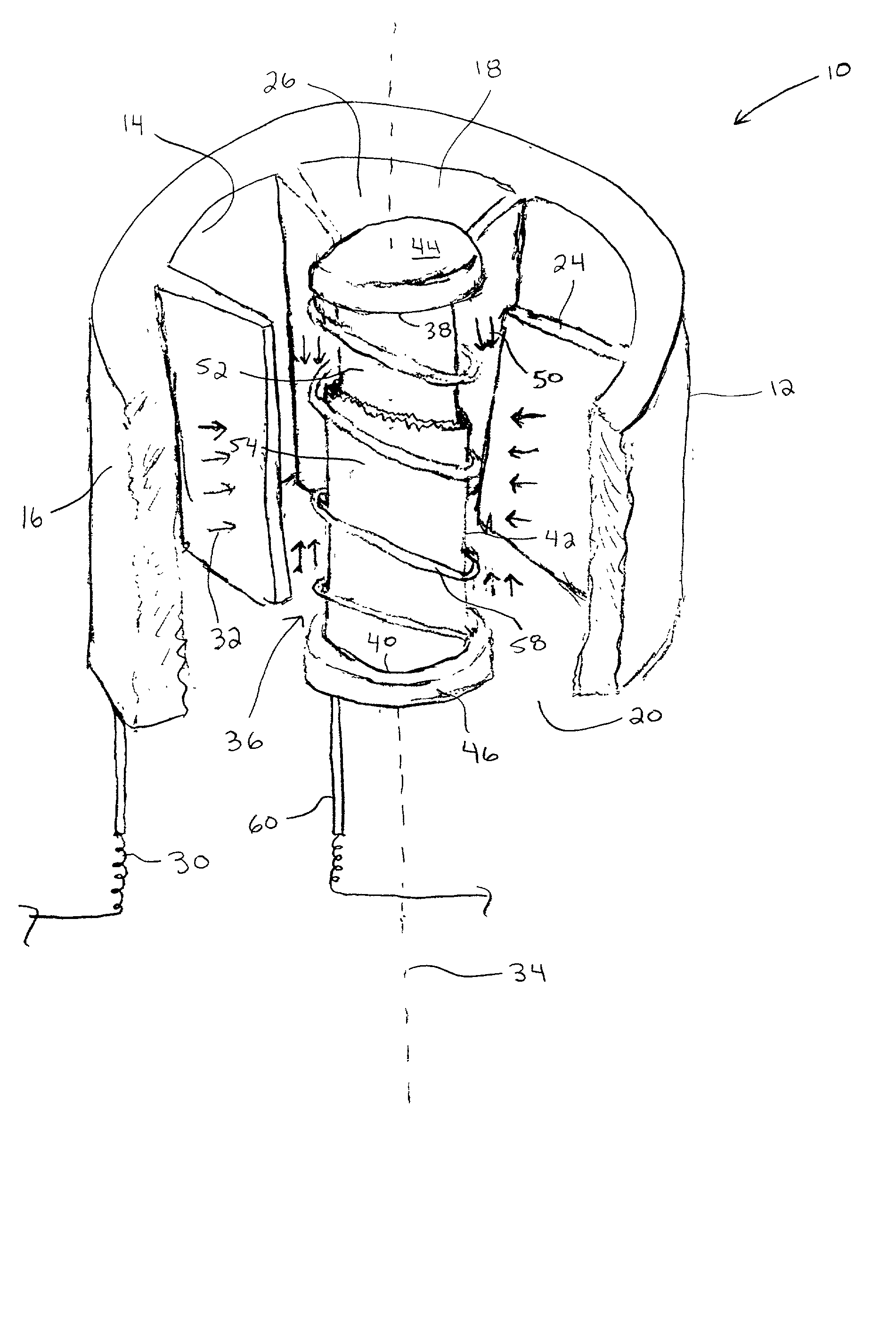
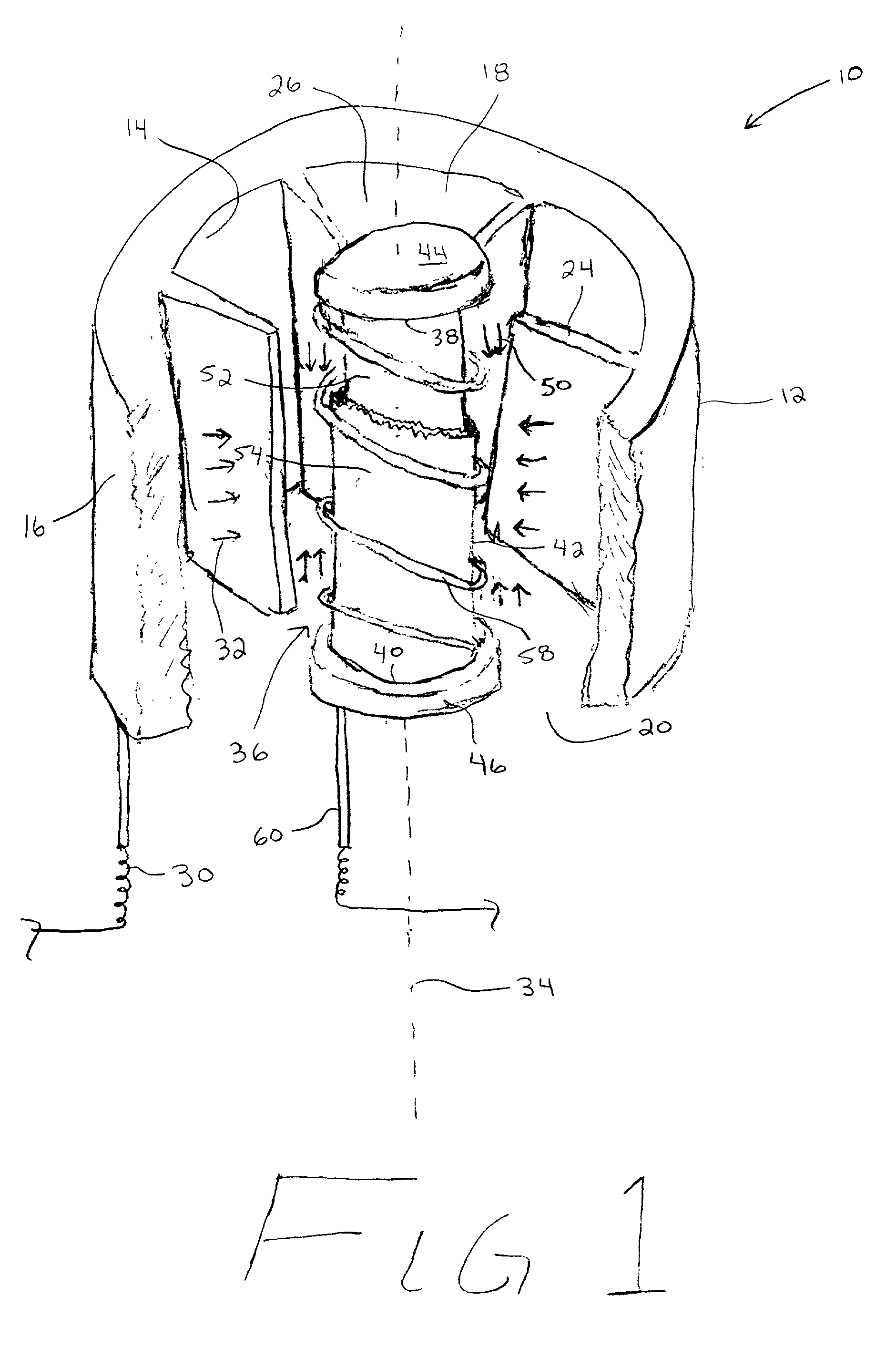
[0027] The present invention is directed toward a radio frequency (RF) magnetron device for generating microwave power capable of relying entirely upon secondary electron emission to sustain operation. In the past RF magnetron devices commonly employed a cathode formed from a tungsten or copper material. In such a configuration, secondary electrons are only capable of generating approximately 60% of the overall electron emission needed for operation. The additional 40...


PUM


Abstract

A radio frequency magnetron device for generating radio frequency power includes a cathode at least partially formed from a diamond material. An anode is disposed concentrically around the cathode. An electron field is provided radially between the anode and the cathode. First and second oppositely charged pole pieces are operatively connected to the cathode for producing a magnetic field in a direction perpendicular to the electric field. A filament is provided within the electron tube which when heated produces primary electrons. Alternatively, a voltage is applied to the anode which causes primary electrons to emit from the diamond coated cathode. A portion of the primary electrons travel in a circular path and induce radio frequency power. Another portion of the primary electrons spiral back and collide with the cathode causing the emission of secondary electrons. The secondary electron emission sustains operation of the magnetron device once the device has been started.

Description

BACKGROUND OF THE INVENTION[0001] 1. Field of the Invention[0002] The present invention relates generally to the art of cross-field microwave electron tubes for converting electron potential energy into high efficiency microwave energy. More specifically, the present invention relates to a radio frequency (RF) magnetron or microwave power tube that utilizes chemical vapor deposited (CVD) diamond as the cathode to increase the secondary electron emission of the magnetron during operation.[0003] 2. Discussion of the Prior Art[0004] Most all vacuum electron tubes require a physical source of electrons which are typically provided by some method of electron emission. General electron emission can be analogized to the ionization of a free atom. Prior to ionization, the energy of electrons in an atom is lower than electrons at rest in a vacuum. In order to ionize the atom, energy must be supplied to the electrons in the atom. That is, the atom fails to spontaneously emit electrons unless ...

Claims


Application Information

Patent Timeline
Patent Type & Authority Applications(United States)
IPC IPC(8): H01J23/05
CPCH01J23/05H01J2201/30457H01J2201/32
Inventor MEARINI, GERALD T.TAKACS, LASZLO A.
Owner TERAPHYSICS CORP
Why Eureka
Try Eureka