Method and apparatus for releasably attaching a polishing pad to a chemical-mechanical planarization machine

Inactive Publication Date: 2002-09-12
MICRON TECH INC
View PDF0 Cites 22 Cited by
  • Summary
  • Abstract
  • Description
  • Claims
  • Application Information

AI Technical Summary

Benefits of technology

0009] The present invention is directed toward a method and apparatus for releasably attaching a planarizing medium to a chemical-mechanical planarization machine. The apparatus can comprise a support and a platen having an engaging surface with one or more vacuum apertures sized and shaped to be coupled to a vacuum source. A planarizing medium can be tightly drawn against the engaging surface of the platen when the vacuum source applies a vacuum to the vacuum apertures. The planarizing medium can include a polishing pad having a generally non-porous surface that seals against the engaging surface of the platen. Alternatively, the planarizing medium can include a porous polishing pad adhesively attached to a pad support. The pad support may have a generally non-porous surface opposite the polishing pad that seals against the platen when the vacuum source is activated. In yet another alternative aspect of the invention, the polishing pad and the pad support can be supported, for example, in a support jig, to condition the polishing pad. In stil

Problems solved by technology

Focusing photo-patterns of such small tolerances, however, is difficult when the planarized surface of the wafer is not uniformly planar.
One problem with conventional CMP processing techniques is that the planarized surface of the wafer may not be sufficiently uniform due to non-uniformities that may develop in the planarizing surface of the polishing pad during planarization.
One drawback with this approach is that the pla

Method used


Image

  • Method and apparatus for releasably attaching a polishing pad to a chemical-mechanical planarization machine
  • Method and apparatus for releasably attaching a polishing pad to a chemical-mechanical planarization machine
  • Method and apparatus for releasably attaching a polishing pad to a chemical-mechanical planarization machine

Examples


Embodiment Construction

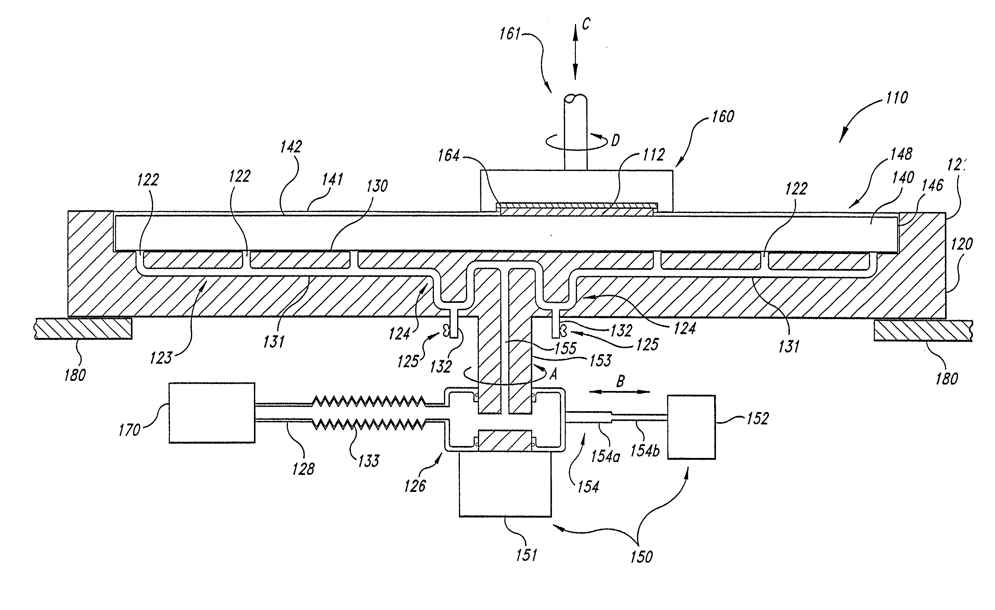
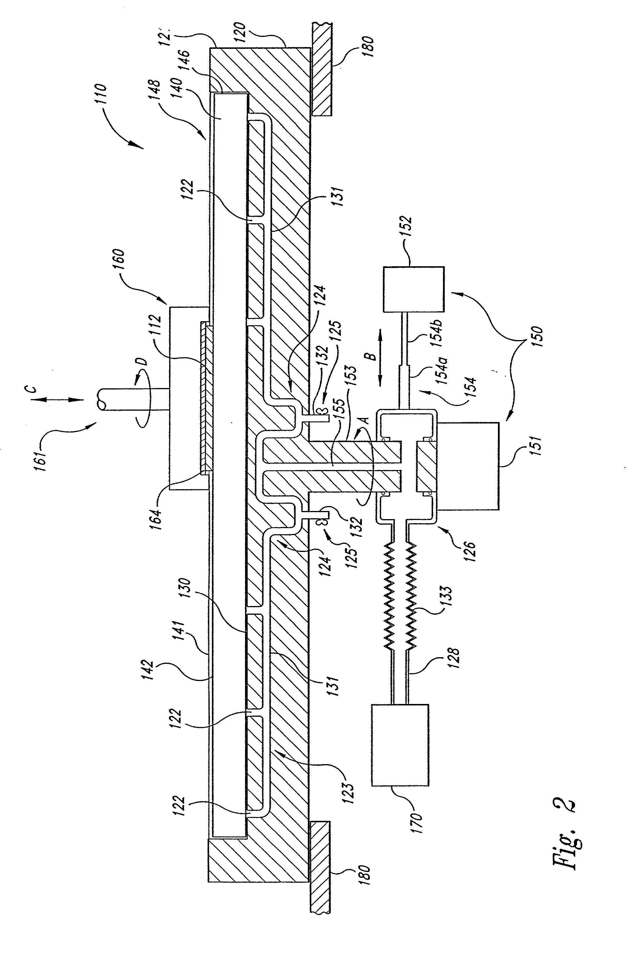
[0021] The present invention is directed toward methods and devices for attaching a polishing pad to a platen of a chemical-mechanical planarization machine. The device may include a vacuum system that releasably attaches the polishing pad to the platen such that the polishing pad may be easily removed and / or replaced, or may be incrementally advanced over the platen. Many specific details of certain embodiments of the invention are set forth in the following description and in FIGS. 2-7 to provide a thorough understanding of such embodiments. One skilled in the art, however, will understand that the present invention may have additional embodiments and that they may be practiced without several of the details described in the following description.

[0022] FIG. 2 illustrates a CMP apparatus 110 having a platen 120 and a planarizing medium 148. In the embodiment shown in FIG. 2, the planarizing medium 148 includes polishing pad 140 releasably attached to the platen 120, and in other e...


PUM

PropertyMeasurementUnit
Poweraaaaaaaaaa
Flexibilityaaaaaaaaaa
Shapeaaaaaaaaaa

Abstract

A method and apparatus for releasably attaching a planarizing medium, such as a polishing pad, to the platen of a chemical-mechanical planarization machine. In one embodiment, the apparatus can include several apertures in the upper surface of the platen that are coupled to a vacuum source. When a vacuum is drawn through the apertures in the platen, the polishing pad is drawn tightly against the platen and may therefore be less likely to wrinkle when a semiconductor substrate is engaged with the polishing pad during planarization. When the vacuum is released, the polishing pad can be easily separated from the platen. The apparatus can further include a liquid trap to separate liquid from the fluid drawn by the vacuum source through the apertures, and can also include a releasable stop to prevent the polishing pad from separating from the platen should the vacuum source be deactivated while the platen is in motion. In another embodiment, a signal can be applied to the platen to draw the polishing pad toward the platen via electrostatic or electromagnetic forces. In still another embodiment, the polishing pad can be attached to a pad support and conditioned on a separate jig.

Description

TECHNICAL FIELD[0001] The present invention relates to methods and devices for releasably attaching polishing pads to the platens of chemical-mechanical planarization machines.BACKGROUND OF THE INVENTION[0002] Chemical-mechanical planarization ("CMP") processes remove material from the surface of a semiconductor wafer in the production of integrated circuits. FIG. 1 schematically illustrates a CMP machine 10 with a platen 20, a wafer carrier 60, a polishing pad 40, and a planarizing liquid 41 on the polishing pad 40. The polishing pad 40 may be a conventional polishing pad made from a continuous phase matrix material (e.g., polyurethane), or it may be a fixed abrasive polishing pad made from abrasive particles fixedly dispersed in a suspension medium. The planarizing liquid 41 may be a conventional CMP slurry with abrasive particles and chemicals that etch and / or oxidize the wafer, or the planarizing liquid 41 may be a planarizing solution without abrasive particles that contains on...

Claims


Application Information

Patent Timeline
IPC IPC(8): B24B37/11B24B37/14B24D9/08B25B11/00
CPCB24B37/11B24B37/14B24D9/085B25B11/005
Inventor DOAN, TRUNG TRIMOORE, SCOTT E.
Owner MICRON TECH INC
Why Eureka
Try Eureka