Various diseases of blood vessels or hollow organs cause a
stenosis or complete obturation (
occlusion) of their lumen, which results in a decrease or complete loss of their functional attributes.
The problem of designing such devices has already a twenty year history.
Nevertheless, a universally reliable device satisfying all necessary requirements has as yet not been created.
Furthermore, the device can withstand only limited external compression forces.
The use of the known device in vessels and hollow organs with a
diameter exceeding 8 mm, and without exceeding the ultimate strain of the frame material, would demand a decrease of the thickness of the
wire frame elements, which would result in a further loss of stiffness of the frame.
Alternatively, it would be necessary to increase the
diameter of the puncture hole, which in turn would cause intolerable trauma to the vascular or hollow organ walls.
However, the making of the frame with a minimum lead between coils results in a loss of its stiffness in the vessel or hollow organ.
In the process of uncoiling, which is uncontrolled, trauma to the vascular or hollow organ walls may occur, which has an unfavorable affect on the result of operation.
In addition, the frame can occupy an arbitrary position in the vessel that is uncontrolled by the surgeon.
The use of this device in arterial vessels is hardly possible because of the large distances between the wire elements, which may result in
germination of atherosclerotic patches and, as a consequence, in an ineffective use of this device.
However, the loss in
diameter thickness may hardly provide an effective means for sustaining the lumen.
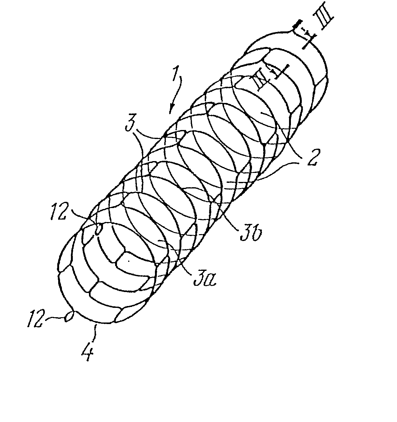
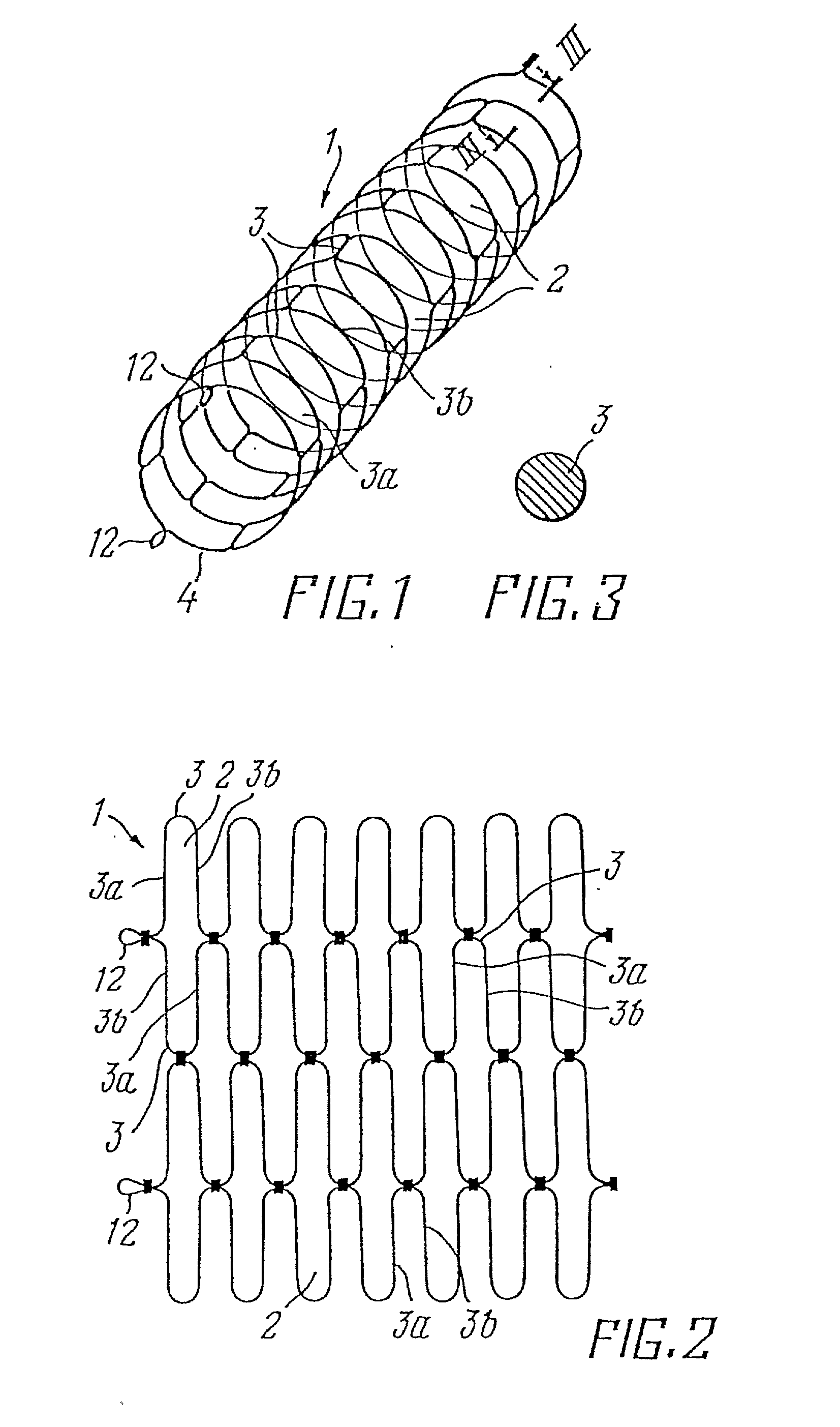
Due to the arrangement of the wire branches in the
peripheral direction of the tubular frame body, the given construction is stable and has a
high stiffness in the axial direction, which prevents full adjustment of the vessel geometry and may traumatize the vascular or hollow organ walls.
When it is necessary to deliver the above device to the affected area along a curved path, the elastic deformation of the frame wire elements changes into plastic deformation, which results in an irreversible change of the device shape.
However, the use of a rigid joint by fusing together,
soldering or
welding of the wire elements in the points of their intersection seems to be unreliable because of:
a probable proceeding of electrochemical processes in the
soldering zone, which may cause damage to the joint, loss of stiffness in the frame and consequently, loss of its functional attributes; and
When it is necessary to deliver the device to the affected area along a curved path, a danger arises to exceed the ultimate elastic strain and, consequently, the proceeding of the process of plastic deformation of the frame material.
Thus, the delivery of the given frame is possible only along a path close to a straight line, which essentially decreases the possibility of its use in different anatomic areas.
The known device has a large stiffness in the axial direction which may traumatize the walls of the vascular or hollow organ in the regions around the ends of the device if the device supports a vascular or hollow organ which changes its shape during
adaptation to varying external loads.
Further, it is a common
disadvantage of the known devices that they possess limited radial stiffness, which allows them to support only vascular or hollow organs that are not surrounded by a
bone structure taking up external loads.

