Chemical vapor deposition apparatus

a chemical vapor deposition and apparatus technology, applied in chemical vapor deposition coatings, coatings, metallic material coating processes, etc., can solve the problems of reduced process yield, increase in semiconductor fabrication costs, and low deposition rate of conventional chemical vapor deposition apparatus, and achieve excellent step coverage and film quality characteristics. , the effect of fast deposition ra

Inactive Publication Date: 2002-09-19
WONIK IPS CO LTD
View PDF11 Cites 354 Cited by
  • Summary
  • Abstract
  • Description
  • Claims
  • Application Information

AI Technical Summary

Benefits of technology

0013] An object of the present invention is to provide a chemical vapor deposition apparatus which uses radicals of reactant gases while supplying process gases in sequence by generating plasma within a showerhead or injecting exterior plasma into a chamber

Problems solved by technology

However, the technology using such a conventional chemical vapor deposition apparatus has a disadvantage of a very low deposition rate, and becomes a cause of increase in fabrication costs of a semiconductor when it is applied to a mass-production process of the semiconductor.
However, there is a disadvantage in that the substrate and circuit elements formed on the

Method used


Image

  • Chemical vapor deposition apparatus
  • Chemical vapor deposition apparatus
  • Chemical vapor deposition apparatus

Examples


first embodiment

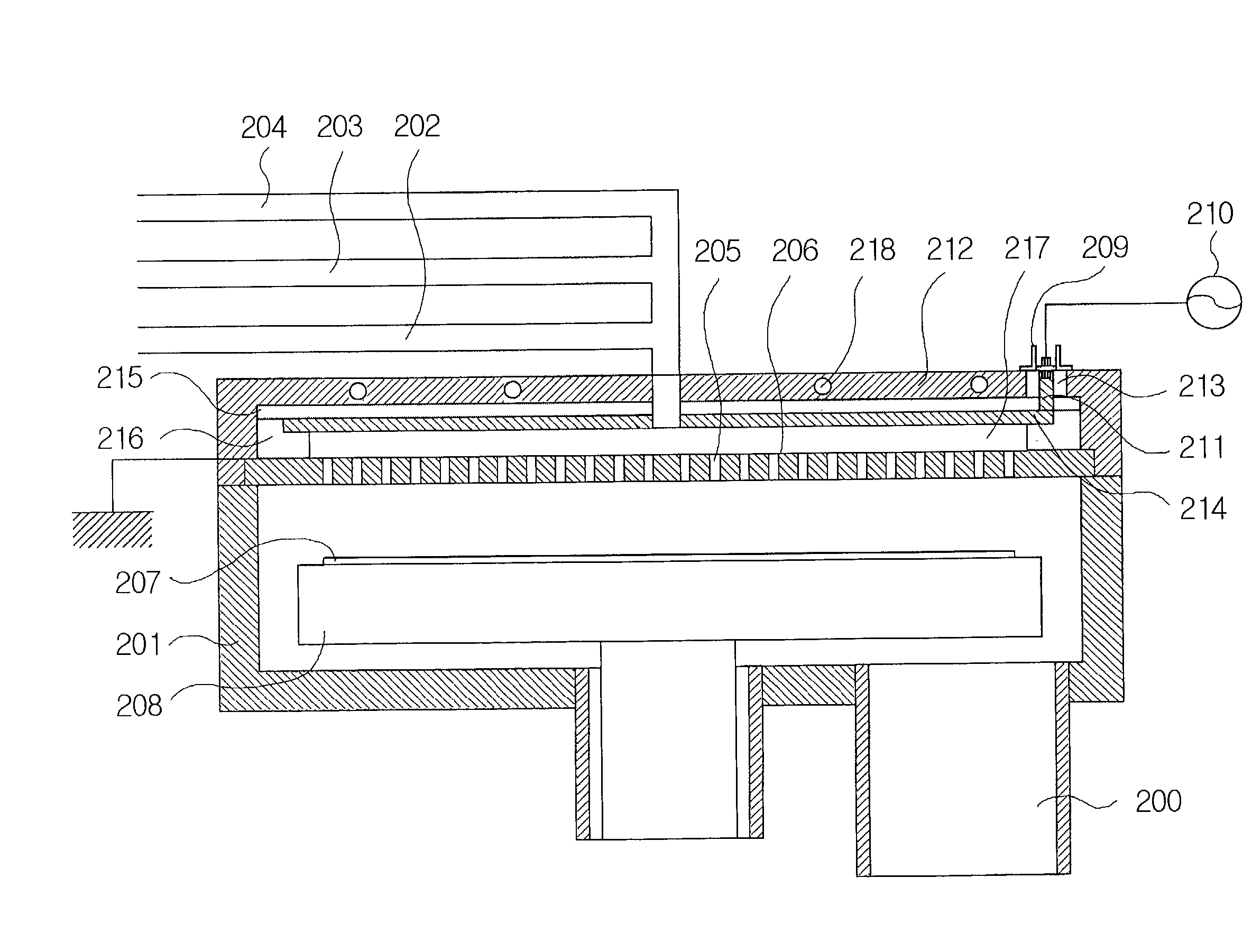
[0039] FIG. 2A is a schematic view showing constitutional elements of a radical assisted chemical vapor deposition apparatus in which process gases are sequentially supplied according to the present invention.

[0040] As can be seen in this figure, the chemical vapor deposition apparatus of the present invention is constructed such that a thin film is formed by sequential supply of process gases consisting of the processes of injecting and purging source gases and injecting and purging reactant gases, where the reactant gases are injected in a state where plasma is generated within a showerhead upon their injection.

[0041] As shown in FIG. 2A, in the chemical vapor deposition apparatus of the present invention, an upper plate 212 is mounted on the top of a chamber 201 for constituting a portion of the chamber 201, and an RF power source connection portion 209 which can be connected to an external RF power source 210 is installed on a side of the upper plate 212. The RF power source con...

second embodiment

[0056] FIG. 3A is a schematic view showing constitutional elements of a radical assisted chemical vapor deposition apparatus in which the process gases are sequentially supplied and the plasma is generated in an upper portion of a showerhead partitioned into a predetermined pattern according to the present invention.

[0057] As can be seen from this figure, the chemical vapor deposition apparatus of the present invention is constructed such that a thin film is formed by sequentially supplying the process gases using the processes of injecting and purging the source gases and injecting and purging the reactant gases; that mixing of the source gases with the reactant gases is completely prevented within the showerhead by partitioning the showerhead into two sections to separate a first section where the source gases are introduced and injected from a second section where the reactant gases are introduced and injected; and that upon injection of the reactant gases, the radicals of the re...

third embodiment

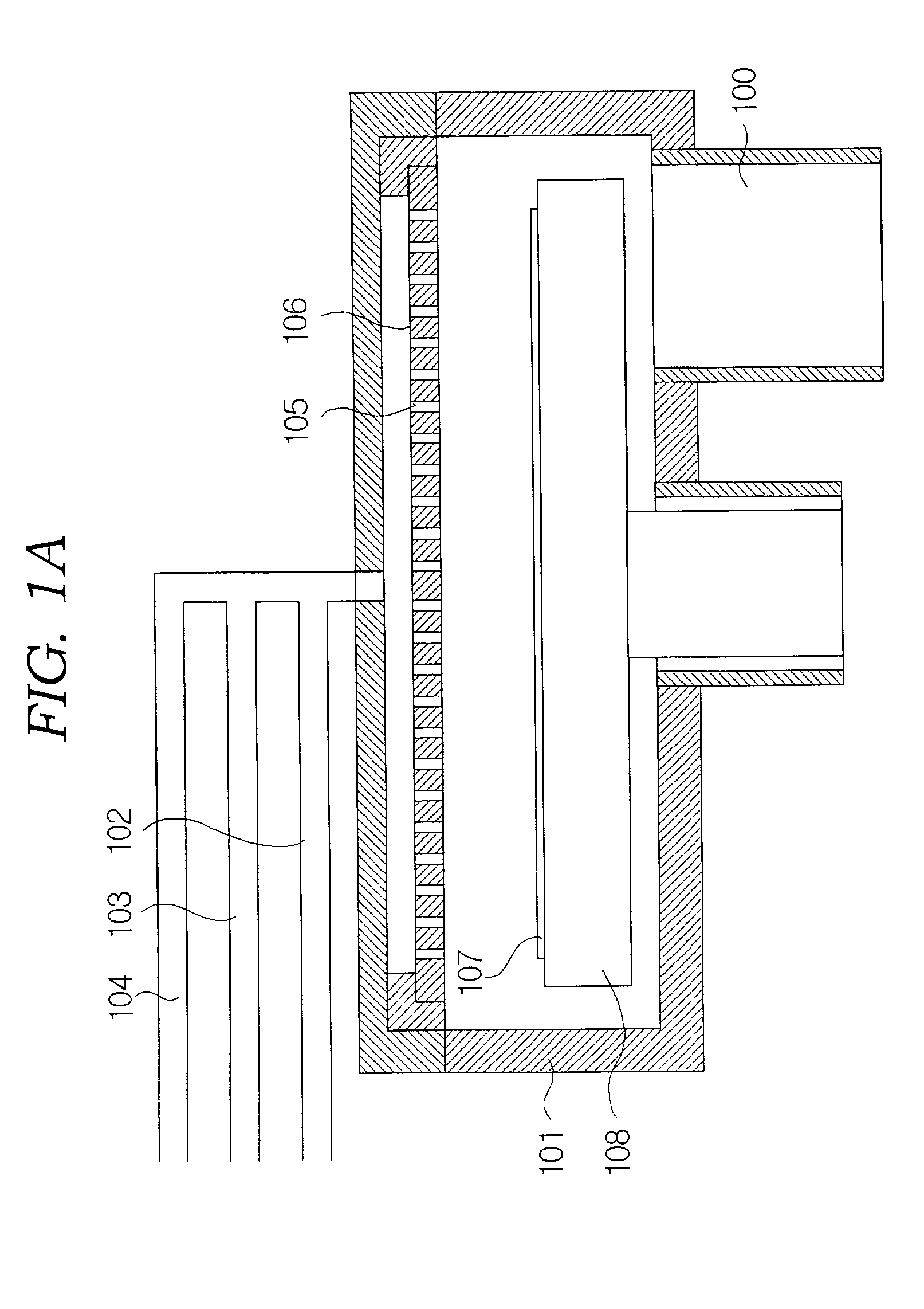
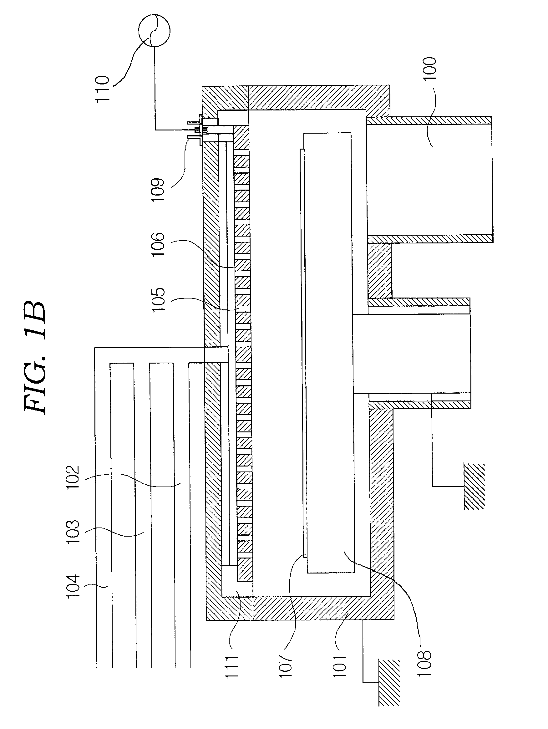
[0071] FIG. 4 is a schematic view showing constitutional elements of a chemical vapor deposition apparatus in which the process gases are sequentially supplied and an external plasma generating apparatus is employed according to the present invention.

[0072] As shown in this figure, the chemical vapor deposition apparatus of the present invention comprises a chamber 401 with an outlet 400 disposed at a lower portion thereof, a showerhead 406 with a plurality of injection holes 405 formed therein for injecting the process gases, and a heater 408 for supporting a wafer or substrate 407 (hereinafter, referred to as "substrate") on which a thin film is deposited with the process gases injected through the showerhead 406 and for simultaneously functioning as a heat source.

[0073] An upper plate 409 is mounted on the top of the chamber 401 for constituting a portion of the chamber 401. An external plasma generating apparatus 410 is connected with the chamber 401 to communicate with each oth...


PUM

PropertyMeasurementUnit
Temperatureaaaaaaaaaa

Abstract

The present invention relates to chemical vapor deposition apparatus. In the chemical vapor deposition apparatus, an RF power source connection portionconnected to an external RF power source is installed on an upper side of a chamber; an RF electrode plate is installed within the chamber to be spaced with a predetermined gap from an inner upper surface of the chamber and to be spaced with a predetermined gap from a showerhead disposed below the RF electrode plate; plasma is generated in a first buffer portion, which is defined by a gap between the RF electrode plate and an upper surface of the showerhead, by means of the electric power applied from the external RF power source to the RF electrode plate; the showerhead is divided into two sections in a vertical direction and a second buffer portion is defined by a space between the two sections; reactant gases are supplied to the first buffer portion in which the plasma is generated; and source gases are supplied to the second buffer portion.

Description

BACKGROUND OF THE INVENTION[0001] 1. Field of the Invention[0002] The present invention relates to a chemical vapor deposition (CVD) apparatus, and more particularly, to a chemical vapor deposition apparatus which uses radicals of reactant gases while supplying process gases in sequence by generating plasma within a showerhead or injecting exterior plasma into a chamber through the showerhead.[0003] 2. Description of the Prior Art[0004] Generally, in order to obtain excellent step coverage and film quality characteristics at low temperature, source gases and reactant gases are supplied to a chemical vapor deposition apparatus in sequence. Herein, a conventional chemical vapor deposition apparatus in which process gases are sequentially supplied will be briefly described with reference to FIGS. 1A to 1C.[0005] FIG. 1A is a schematic view showing constitutional elements of the conventional chemical vapor deposition apparatus in which the process gases are sequentially supplied. As sho...

Claims


Application Information

Patent Timeline
IPC IPC(8): C23C16/455C23C16/44C23C16/515H01L21/205
CPCC23C16/45514C23C16/45538C23C16/45544C23C16/45565C23C16/4557C23C16/45574C23C16/515
Inventor KIM, JAE-HOPARK, SANG-JOON
Owner WONIK IPS CO LTD
Why Eureka
Try Eureka