Method for preparing tungsten trioxide (WO3) electrochromic films
An electrochromic, thin-film technology, applied in instrumentation, nonlinear optics, optics, etc., can solve the problems of rarely disclosed thin films, and achieve the effects of low cost, fast film growth, and fast deposition.
- Summary
- Abstract
- Description
- Claims
- Application Information
AI Technical Summary
Problems solved by technology
Method used
Image
Examples
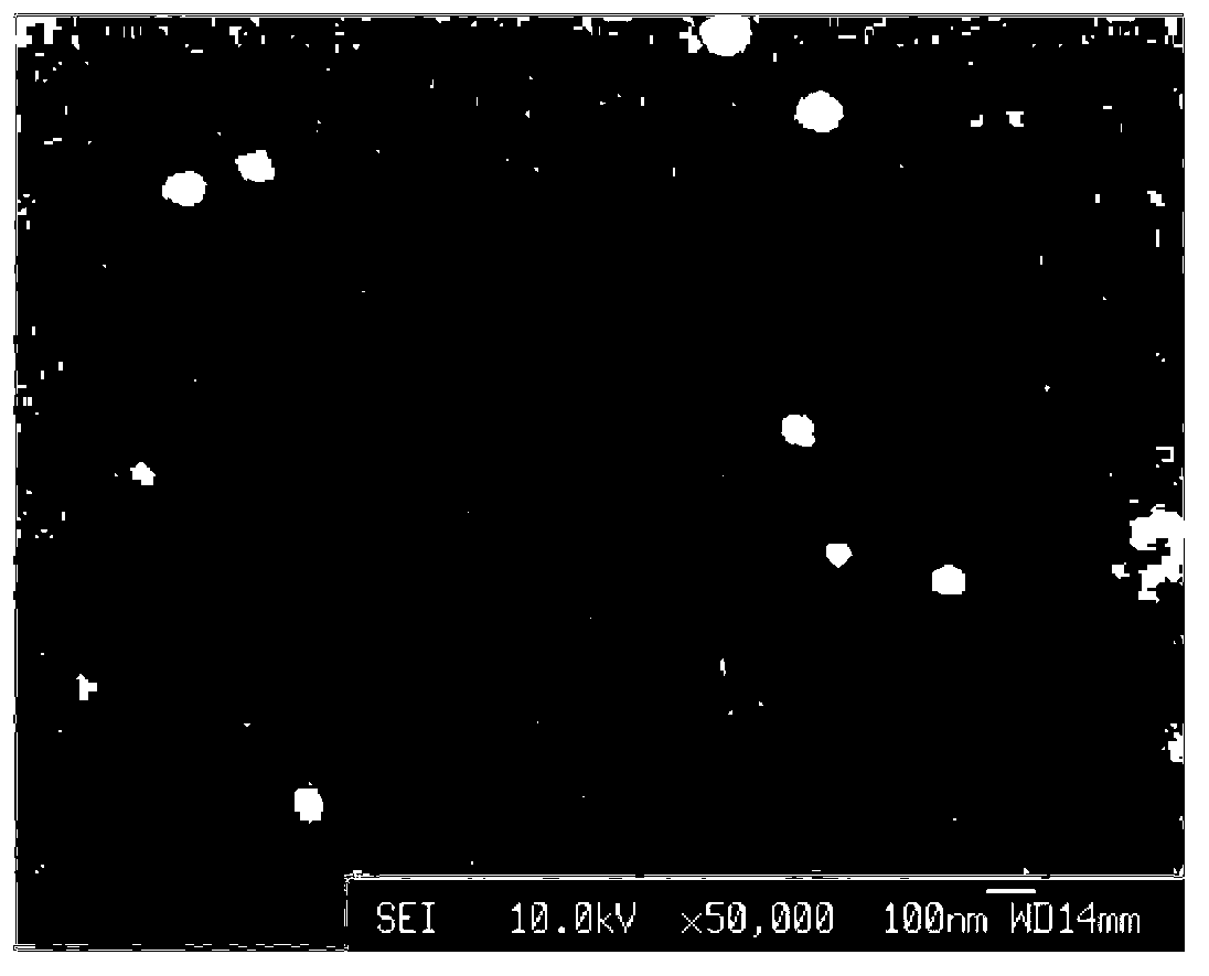
Embodiment 1
[0034]Using radio frequency magnetron sputtering deposition thin film technology, with WO 3 Ceramic is used as the cathode target, and WO is deposited on ITO conductive glass 3 Thin film, the target is a circular WO with a diameter of 76.2mm and a thickness of 3mm 3 ceramic target. The specific operation steps are:
[0035] Step 1. ITO conductive glass pretreatment: immerse the ITO conductive glass substrate in acetone, absolute ethanol and deionized water in sequence for ultrasonic cleaning for 10 minutes, and then dry it with cold air;
[0036] Step 2. Fix the cleaned ITO glass on the RF magnetron sputtering substrate platform, with the side coated with the ITO film facing down. WO 3 The ceramic target is installed on the target position in the vacuum chamber of the radio frequency magnetron sputtering equipment. The target base distance was adjusted to 5cm. After the vacuum chamber is closed, turn on the mechanical pump, open the side pumping valve, and evacuate the v...
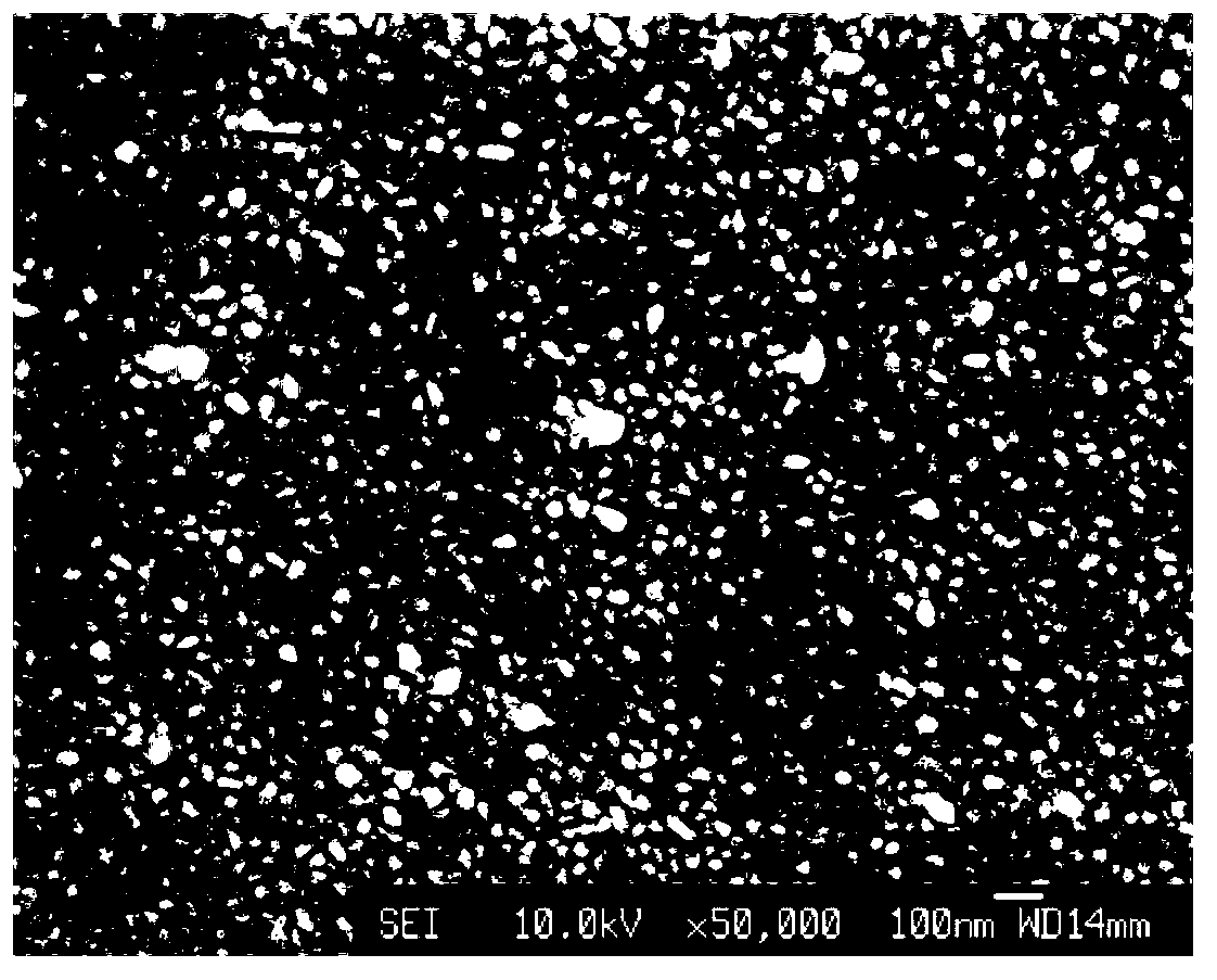
Embodiment 2
[0043] Using radio frequency magnetron sputtering deposition thin film technology, with WO 3 Ceramic is used as the cathode target, and WO is deposited on ITO conductive glass 3 Thin film, the target is a circular WO with a diameter of 76.2mm and a thickness of 3mm 3 ceramic target. The specific operation steps are:
[0044] Step 1. ITO conductive glass pretreatment: immerse the ITO conductive glass substrate in acetone, absolute ethanol and deionized water in sequence for ultrasonic cleaning for 20 minutes, and then dry it with cold air;
[0045] Step 2. Fix the cleaned ITO glass on the RF magnetron sputtering substrate platform, with the side coated with the ITO film facing down. WO 3 The ceramic target is installed on the target position in the vacuum chamber of the radio frequency magnetron sputtering equipment. The target base distance was adjusted to 10cm. After the vacuum chamber is closed, turn on the mechanical pump, open the side pumping valve, and evacuate the...
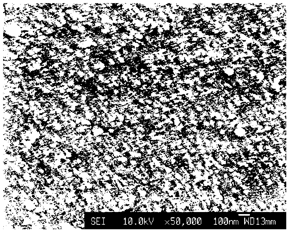
Embodiment 3
[0052] Using radio frequency magnetron sputtering deposition thin film technology, with WO 3 Ceramic is used as the cathode target, and WO is deposited on ITO conductive glass 3 Thin film, the target is a circular WO with a diameter of 76.2mm and a thickness of 3mm 3 ceramic target. The specific operation steps are:
[0053] Step 1. ITO conductive glass pretreatment: immerse the ITO conductive glass substrate in acetone, absolute ethanol and deionized water in sequence for ultrasonic cleaning for 15 minutes, and then dry it with cold air;
[0054] Step 2. Fix the cleaned ITO glass on the RF magnetron sputtering substrate platform, with the side coated with the ITO film facing down. WO 3 The ceramic target is installed on the target position in the vacuum chamber of the radio frequency magnetron sputtering equipment. The target base distance is adjusted to 7.5cm. After the vacuum chamber is closed, turn on the mechanical pump, open the side pumping valve, and evacuate the...
PUM
| Property | Measurement | Unit |
|---|---|---|
| diameter | aaaaa | aaaaa |
| thickness | aaaaa | aaaaa |
Abstract
Description
Claims
Application Information
 - R&D
- Intellectual Property
- Life Sciences
- Materials
- Tech Scout
- Unparalleled Data Quality
- Higher Quality Content
- 60% Fewer Hallucinations
Browse by: Latest US Patents, China's latest patents, Technical Efficacy Thesaurus, Application Domain, Technology Topic, Popular Technical Reports.
© 2025 PatSnap. All rights reserved.Legal|Privacy policy|Modern Slavery Act Transparency Statement|Sitemap|About US| Contact US: help@patsnap.com


