
Closing structure of a dispensing container

a technology of liquid dispensing container and closing structure, which is applied in the direction of packaging foodstuffs, caps, packaged goods, etc., can solve the problems of allergic reaction, eye inflammation or damage, hair falling off,

Inactive Publication Date: 2002-09-19
TAISEI KAKO CO LTD +1
View PDF3 Cites 60 Cited by
  • Summary
  • Abstract
  • Description
  • Claims
  • Application Information

AI Technical Summary

Benefits of technology

[0014] Even if internal pressure of the container should rise in smaller amount than a predetermined amount, the rise of the internal pressure is modified and the orifice of the dispensing valve is kept closed, because the valve head is shifted downstream owing to the closing structure according to the first aspect described above, preventing undesired outflow of fluid in storing or handling. The contamination of fluid from external cause is prevented because fluid remaining in the downstream end portion of the passage, which is on the downstream side of the filter, is sucked back to the upstream side of the filter through the restoring force of the valve. The filter should preferably be one that is able to prevent predetermined kinds of microbes such as bacteria and true fungi from passing through from the downstream side (i.e., outside of the container) to the upstream side (i.e., inside of the container). For example, a membrane filter is preferred.
[0016] Owing to this aspect, the fluid in the container is effectively protected against the attack of microbes in the ambient air because of liquid-tightness and air-tightness when the orifice of the valve is closed, because the orifice is defined by the valve head itself. The valve head is made of elastic material such as rubber to be deformable so that it is able to open and close the orifice. The container is constituted by the outer bottle and the inner bag, which generates a negative pressure in the inner bag after dispensing fluid. The supporter prevents the valve head from opening the orifice through inward deformation by the negative pressure, thus preventing ambient air and the liquid that is once discharged through the valve from entering through the valve and into the bag, obviating the need of preservatives in the liquid in the bag.

Problems solved by technology

However, various problems resulting from side effects of the preservatives have been pointed out recently.
For example, repetitive use of eyedrops containing preservatives might cause inflammation or damage of eyes.
Especially for those wearing contact lenses, use of eyedrops containing preservatives even in low density might cause allergic reaction.
Some preservatives contained in shampoo are pointed out to have possibility of causing inflammation of scalp or falling off of hair.
Furthermore, consumers of recent years tend to dislike and avoid contained preservatives themselves.
However, such prior art containers cannot fully lower the density of preservatives if the eyedrops contain enough amount of preservatives to achieve sufficient sterilization effect.
More specifically, because microbes in the ambient air are allowed to come to be mixed in the liquid within the above-described eyedrops container and the microbes mixed in the liquid are sterilized with the preservatives, it is impossible to fully lower the density of preservatives in the liquid, therefore, some amount of preservatives remains in the eyedrops to be discharged dropwise.
The filter allows the ophthalmic liquid medicament to pass through and does not allow air and bacteria to pass through.
However, the eyedrops container cannot have transparency because the body of the container cannot be made of plastic material but should be made of aluminum tube and the like, as plastic deformation of the container body of monolayer structure is required.
Therefore, remaining amount of the eyedrops cannot be seen from outside.
Furthermore, it cannot be kept upright since the container body is deformed compressedly as the contained liquid is consumed, thus spoiling convenience in use.
However, liquid remaining in the discharge opening on the downstream side of the check valve may be contaminated by microbes such as true fungi, bacteria and viruses as the liquid is exposed to the ambient air, thus incurring possibility of dispensing contaminated liquid.

Method used


Image

  • Closing structure of a dispensing container
  • Closing structure of a dispensing container
  • Closing structure of a dispensing container

Examples


Embodiment Construction

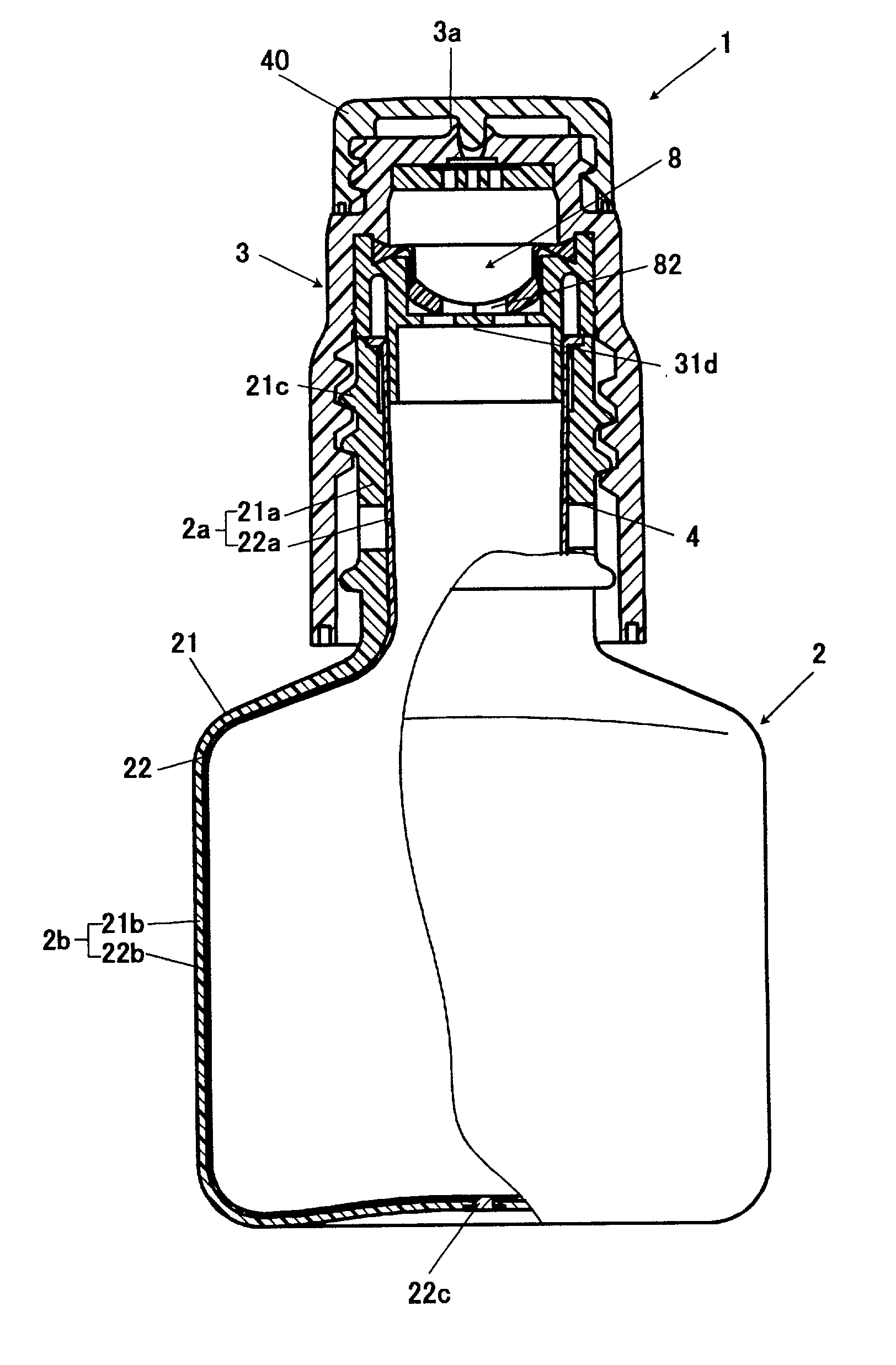
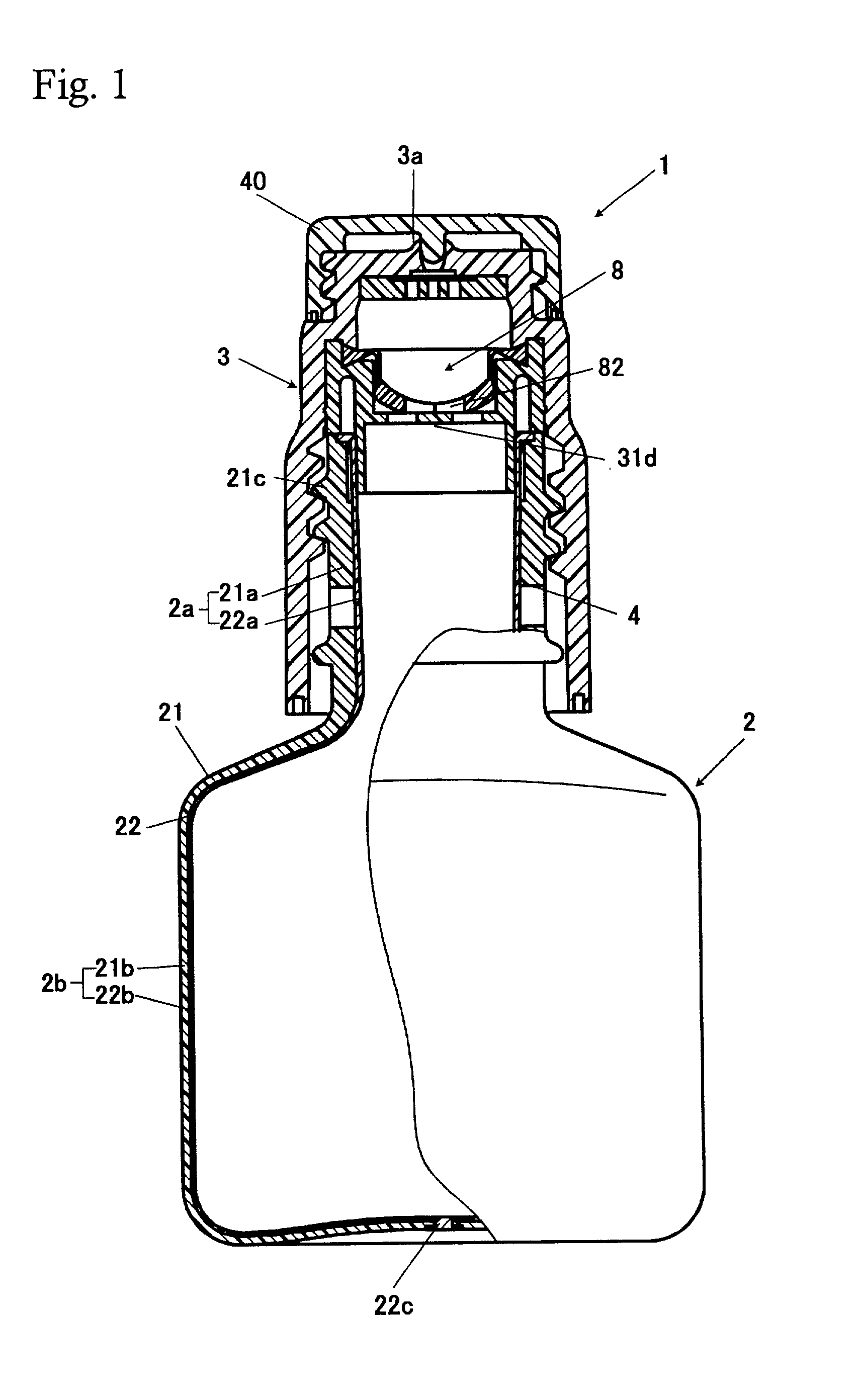
[0032] The closing structure according to this invention may be applied to a dispensing container having an outer bottle including a body and a mouth and an inner bag for containing fluid housed within the outer bottle and having a discharge opening communicating to the mouth of the outer bottle, the outer bottle having a vent to introduce ambient air into space between the outer bottle and the bag.

[0033] Fluid such as eyedrops and detergent is contained in the bag. With the decrease of contained fluid, ambient air flows into the space between the outer bottle and the inner bag through the vent to make the pressure around the bag atmospheric again, whereas the bag deflates or collapses. The inflow of the ambient air into the bag through the discharge opening is prevented by a dispensing valve that also functions as a check valve. Therefore, the container does not introduce the ambient air into the bag, obviating the need of adding preservatives into the fluid in the bag.

[0034] Thoug...


PUM

PropertyMeasurementUnit
diameteraaaaaaaaaa
pressureaaaaaaaaaa
closing structureaaaaaaaaaa

Abstract

A closing member 3 is equipped with a dispensing valve 8 and a filter 7. The valve 8 is deformed resiliently to shift its valve head 82 downstream with its orifice 82a remaining closed if pressure less than a first predetermined pressure and more than a second predetermined pressure is acted on the inner surface of the valve head 82. The valve 8 returns to its original shape to shift the valve head 82 upstream with its orifice 82a remaining closed if the pressure is removed, thereby sucking fluid remaining within the passage 10 back to the upstream side of the filter 7. The closing member 3 has a supporter 31d that prevents the orifice 82a of the valve head 82 from opening when a negative pressure is generated in the bottle.

Description

BACKGROUND OF THE INVENTION[0001] 1. Field of the Invention[0002] The present invention relates to a closing structure of a fluid-dispensing container suitable for an aseptic eyedropper, cosmetic liquid container without antibiotic, or the like. Herein, "fluid" means material capable of flowing, such as fluid or fluidized material, including liquid, paste, powder, and the like.[0003] 2. Description of Related Art[0004] Closing structure of a fluid-dispensing container including a dispensing valve secured in the mouth of one of various types of containers, which remains closed if the pressure in the container is atmospheric and opens if the pressure exceeds a predetermined pressure, is disclosed in each of Japanese Laid-open Patent Application No. Hei. 8-282704, Japanese Laid-open Patent Application No. Hei. 8-282703, U.S. Pat. Nos. 5,213,236, 5,339,995, and 5,439,143.[0005] The above-mentioned closing structure is preferably usable in dispensers of eyedrops, i.e. ophthalmic liquid m...

Claims


Application Information

Patent Timeline
Patent Type & Authority Applications(United States)
IPC IPC(8): A61J1/05B65D83/00A61J1/10B65D23/02B65D41/04B65D47/18B65D47/20B65D77/06
CPCB65D23/02B65D47/18B65D47/2031
Inventor SHIRAISHI, YASUYUKIHAMAMOTO, KEIJIMIHASHI, HIROKAZU
Owner TAISEI KAKO CO LTD
Features
  • Generate Ideas
  • Intellectual Property
  • Life Sciences
  • Materials
  • Tech Scout
  • Unparalleled Data Quality
  • Higher Quality Content
  • 60% Fewer Hallucinations
Learn More