

Brushless DC motor and refrigerant compressor employing the motor
a dc motor and compressor technology, applied in the direction of stator/rotor body manufacturing, magnetic circuit shape/form/construction, windings, etc., can solve the problems of dislocation or breakage of insulating components, likelihood of insulation failure, etc., to minimize the chance of insulation failure and improve productivity
- Summary
- Abstract
- Description
- Claims
- Application Information
AI Technical Summary
Benefits of technology
Problems solved by technology
Method used
Image

Examples
first embodiment
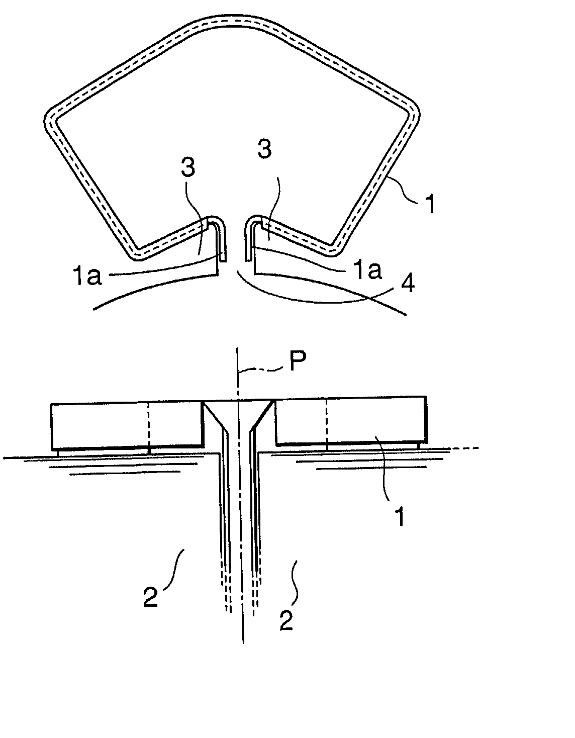
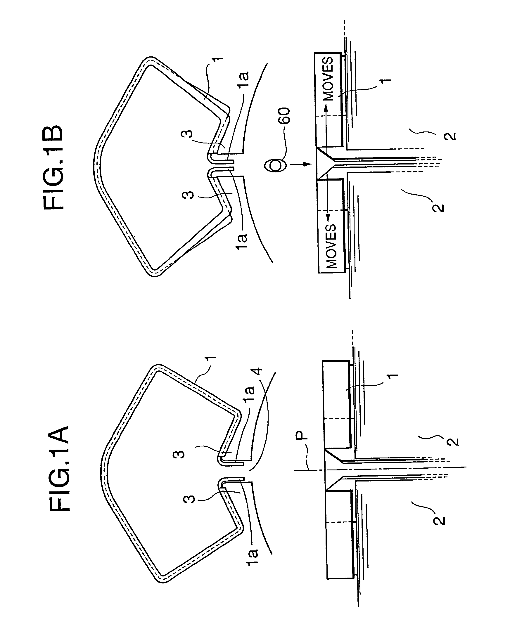
[0088] Embodiments in accordance with the present invention will be described in conjunction with the accompanying drawings. First, the descriptions will be given of a FIG. 1 shows a part of a brushless DC motor of a type called "series winding type" or "concentrated winding type." A sheet-like insulator 1 is formed of, for example, a polyester film having a thickness of about 0.2 mm to about 0.5 mm. As it will be discussed hereinafter, the insulator is folded and disposed between teeth or in a slot aperture such that it lies along inner surfaces of the teeth.
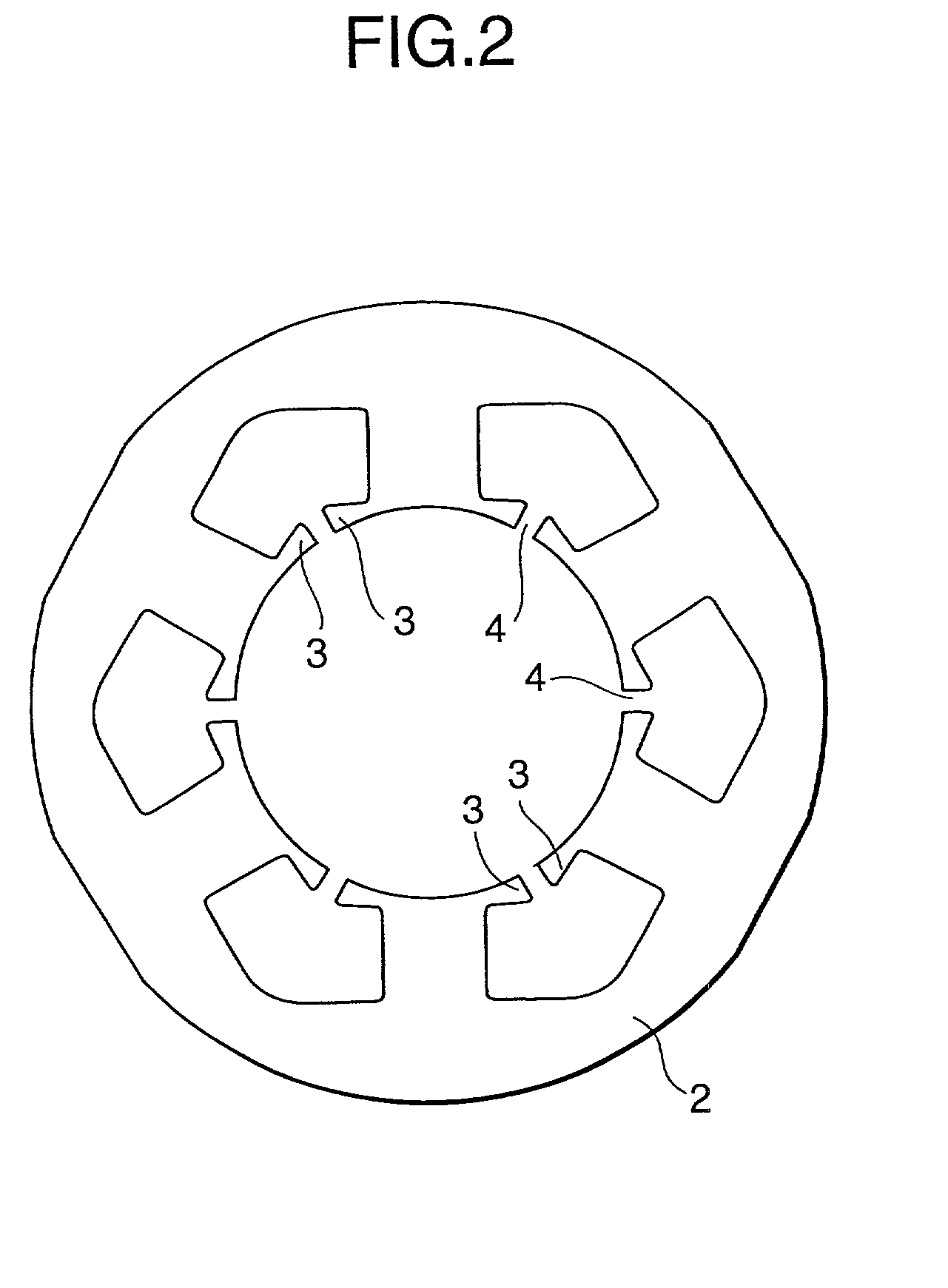
[0089] The brushless DC motor further has an iron core 2 of a stator, teeth 3 of the iron core, and a slot aperture 4 between teeth. FIG. 1 shows a state wherein no winding has been installed. FIG. 2 shows the iron core of the stator, the iron core being a "six-slot type" that has six slots. An aperture of each of the slots is provided with an insulator. FIG. 3 shows the stator of the brushless Dc motor. The stator and a rotor...
third embodiment
[0106] A concentrated winding type brushless DC motor in accordance with a third embodiment will now be described with reference to FIG. 7 through FIG. 10.
[0107] Referring to FIG. 11 and FIG. 12, a conventional concentrated winding type brushless DC motor is constructed by a stator 101 and a rotor 102. The stator has a shape as shown in FIG. 11A, wherein stator plates or silicon steel plates are laminated to form a stator core 111. The stator core 111 is equipped with teeth 112. Each of the teeth 112 has a predetermined width and is provided with tooth distal end portions 113 on its both sides along a surface of the rotor. A drive coil (not shown) is directly wound around the tooth 112 by making use of a space of a slot so as to form a magnetic pole of the stator 101 by the so-called concentrated series winding method. In this example, a 4-pole, 6-slot stator is shown.
[0108] With this arrangement, the stator can be formed to be smaller than the stator of a distributed winding type b...
fourth embodiment
[0118] Referring now to FIG. 13, a concentrated winding type brushless DC motor in accordance with a fourth embodiment will be described.
[0119] A conventional concentrated winding type brushless DC motor is formed as illustrated in FIG. 11 and FIG. 12 as set forth above. The rotor 102 is inserted in the center of the stator 101 formed as described above, then current is supplied to the drive coil of the stator 101 to magnetize the magnet 122 of the rotor 102, thus completing the concentrated winding type brushless DC motor. There has been a shortcoming in that, when magnetizing the brushless DC motor, many short circuit magnetic fluxes are generated between the tooth distal end portions 113 of the stator that oppose each other, leaving less magnetic fluxes that act on a magnet 222 of the rotor, as can be seen from a magnetic flux distribution of FIG. 17.
[0120] As simple measures for reducing the short circuit magnetic fluxes between the opposing tooth distal end portions 113, the di...
PUM
| Property | Measurement | Unit |
|---|---|---|
| Length | aaaaa | aaaaa |
| Length | aaaaa | aaaaa |
| Length | aaaaa | aaaaa |
Abstract
Description
Claims
Application Information