

Vehicle air conditioner with cold storage and cold release
a technology of vehicle air conditioner and cold storage, which is applied in the direction of cooling fluid circulation, domestic cooling apparatus, lighting and heating apparatus, etc., can solve the problems of deficiency of cold storage amount, deterioration of cooling feeling of passenger in passenger compartment, and stoppage of compressor
- Summary
- Abstract
- Description
- Claims
- Application Information
AI Technical Summary
Benefits of technology
Problems solved by technology
Method used
Image

Examples
first embodiment
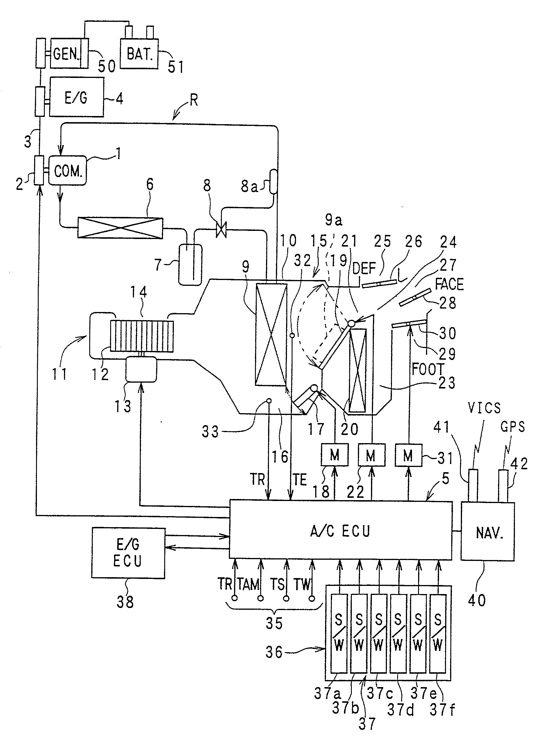
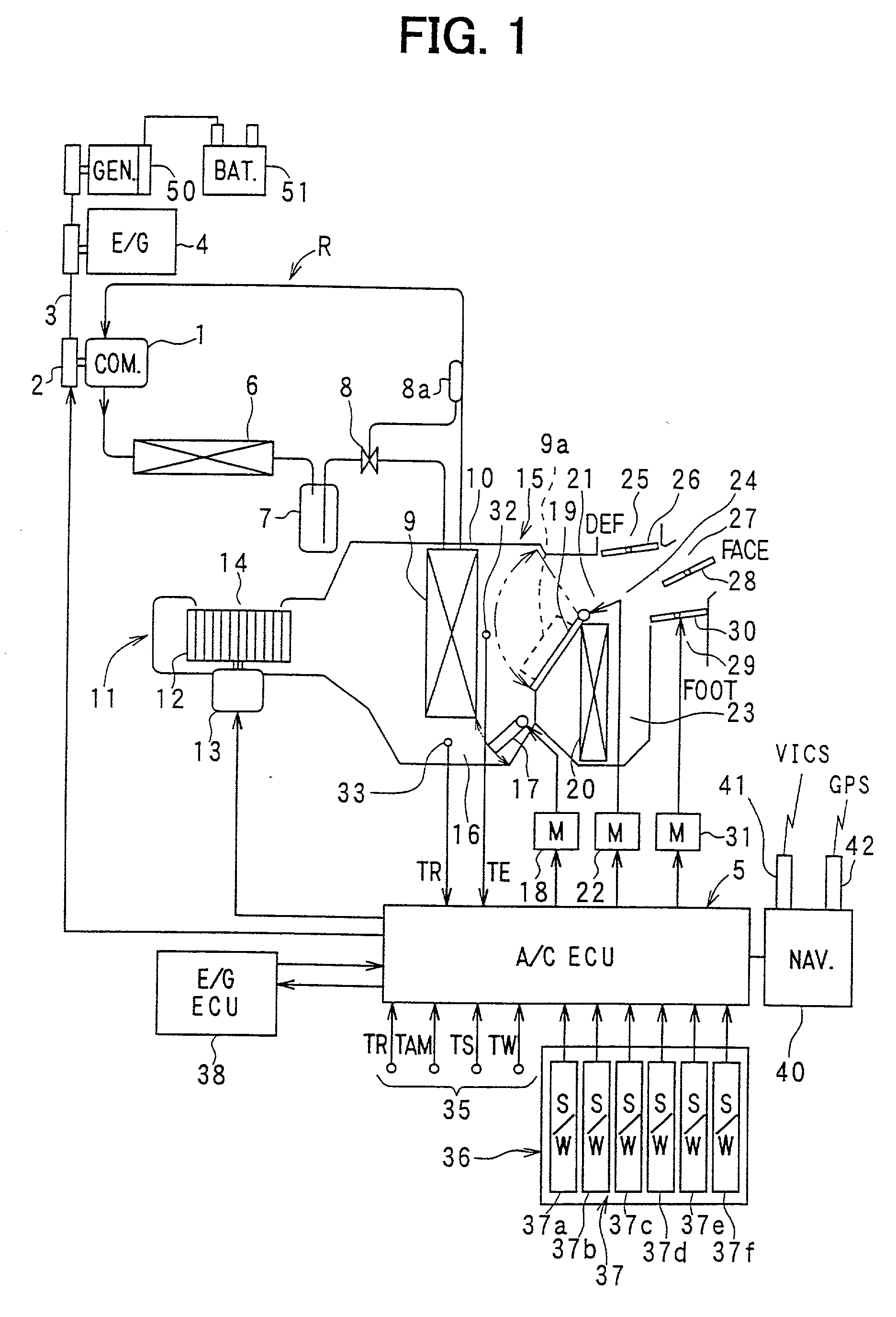
[0031] the present invention will be now described with reference to FIGS. 1-6. As shown in FIG. 1, a refrigerant cycle system R of a vehicle air conditioner includes a compressor 1 for sucking, compressing and discharging refrigerant circulating in the refrigerant cycle system R. The compressor 1 includes a solenoid clutch 2 for interrupting power from a vehicle engine 4. The power of the vehicle engine 4 is transmitted to the compressor 1 through the solenoid clutch 2 and a belt 3. The compressor 1 can be driven also by inertial power of the vehicle. The inertial power of the vehicle can be also recovered as a cold storage by increasing a cold storage amount of condensed water of an evaporator 9 described later.
[0032] Energization for the solenoid clutch 2 is interrupted by an air-conditioning electronic control unit (air-conditioning ECU) 5. The compressor 1 and the engine 4 are connected through the solenoid clutch 2 when the solenoid clutch 2 is energized. When the solenoid clu...
second embodiment
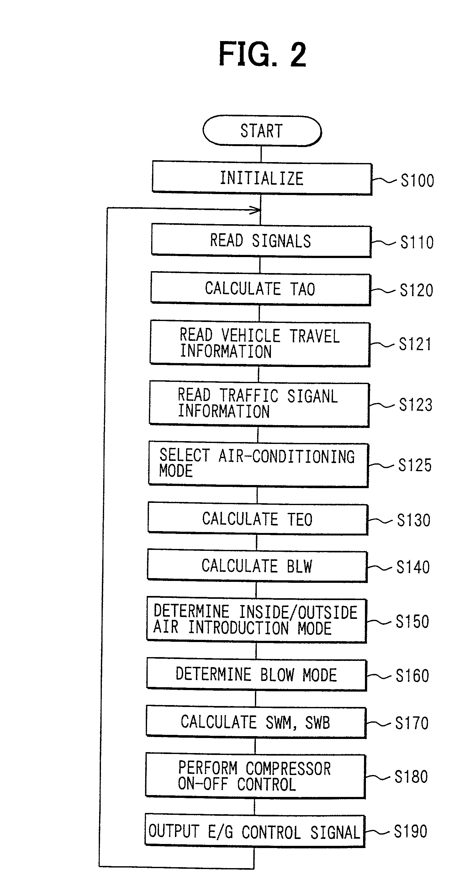
[0083] The control operation of the second embodiment will be now described with reference to the flow diagram of FIG. 9. In FIG. 9, steps similar to those in FIG. 2 are indicated by the same step numbers, and detail explanation thereof is omitted.
[0084] As shown in FIG. 9, at step S124, rotational speed fluctuations of the compressor 1 and the generator 50 in the recovery time zone T3 are estimated using the travel state information and the traffic signal information from the navigation unit 40. Then, fluctuations of the operational efficiency E1, E2 of the compressor 1 and the generator 50 in the recovery time zone T3 are calculated using the estimated rotational speed fluctuations, respectively.
[0085] When the necessary cold release amount Q and the necessary electric power P are not obtained, the recovery time zone T3 is divided to a driving time zone of the compressor 1 and a driving time zone of the generator 50 so that the inertial power can be recovered at high efficiency of...
fourth embodiment
[0094] In the fourth embodiment, alternatively, only when the vehicle speed is equal to or lower than a predetermined speed (e.g., 40 km / h), it can be determined that the vehicle is travelling on the city road at step S200.
[0095] In the fourth embodiment, the cold storage amount may be excessive or deficient due to a switching control between the normal cooling mode and the cold storage mode based on the above determination at step S200. This excess / deficiency result may be used to correct the next determination. That is, when the necessary cold storage amount Q is not obtained, the correction is performed so that the cold storage amount is increased at the next determination. For example, in a case where it is determined that the vehicle is travelling on a city road when the vehicle speed is equal to or lower than 40 km / h, when the cold storage amount is insufficient, the correction is performed at the next determination so that it is determined that the vehicle is travelling on a ...
PUM
 Abstract
Description
Claims
Application Information