Gas diffusion electrode manufacture and MEA fabrication

a technology of gas diffusion electrodes and gas phase fuel cells, which is applied in the manufacture of cell components, adhesive processes with surface pretreatment, and final product manufacturing, etc., can solve the problems of insufficient gas phase fuel cell gas phase fuel cell flooding, and the methods are difficult to scale up to fabricate gas diffusion electrodes with good surface conductivity, gas permeability, and uniformity. , the effect of cvd, pvd and ecd methods

Inactive Publication Date: 2002-09-26
GAS TECH INST
View PDF0 Cites 69 Cited by
  • Summary
  • Abstract
  • Description
  • Claims
  • Application Information

AI Technical Summary

Problems solved by technology

Too little water causes a high internal resistance due to low humidification of the polymeric membrane while too much water causes flooding of the fuel cell by the water.
However, some of these methods are very difficult to scale up to fabricate gas diffusion electrodes with good surface conductivity, gas permeability, uniformity, and long-term hydrophobic and hydrophilic stability.
The CVD, PVD and ECD methods are not useful in a fuel cell with a gas phase fuel because these methods cannot deposit the electrolyte ionomer with the catalyst particles, as a result of which there is no electrolyte between the catalyst particles in the gas phase.
In the fuel cell, the ionic impedance is a main loss in comparison to electrical loss.
Although resulting in good contact between the catalyst layer and the electrolyte membrane, this method is limited to producing only small electrodes due to the problem of catalyst releasing from the substrate.
In addition, it is very difficult to scale up.
Indeed, impregnation of the carbon cloth in accordance with known methods is undesirable because it results in higher internal resistance of the fuel cell.
In addition, the tetrafluoroethylene layer on the carbon cloth has been found to degrade over time.
And, as a result of this loss of tetrafluoroethylene coating effectiveness, the hydrophobicity of the backing reduces with time of the fuel cell operation.

Method used


Image

  • Gas diffusion electrode manufacture and MEA fabrication
  • Gas diffusion electrode manufacture and MEA fabrication
  • Gas diffusion electrode manufacture and MEA fabrication

Examples


Embodiment Construction

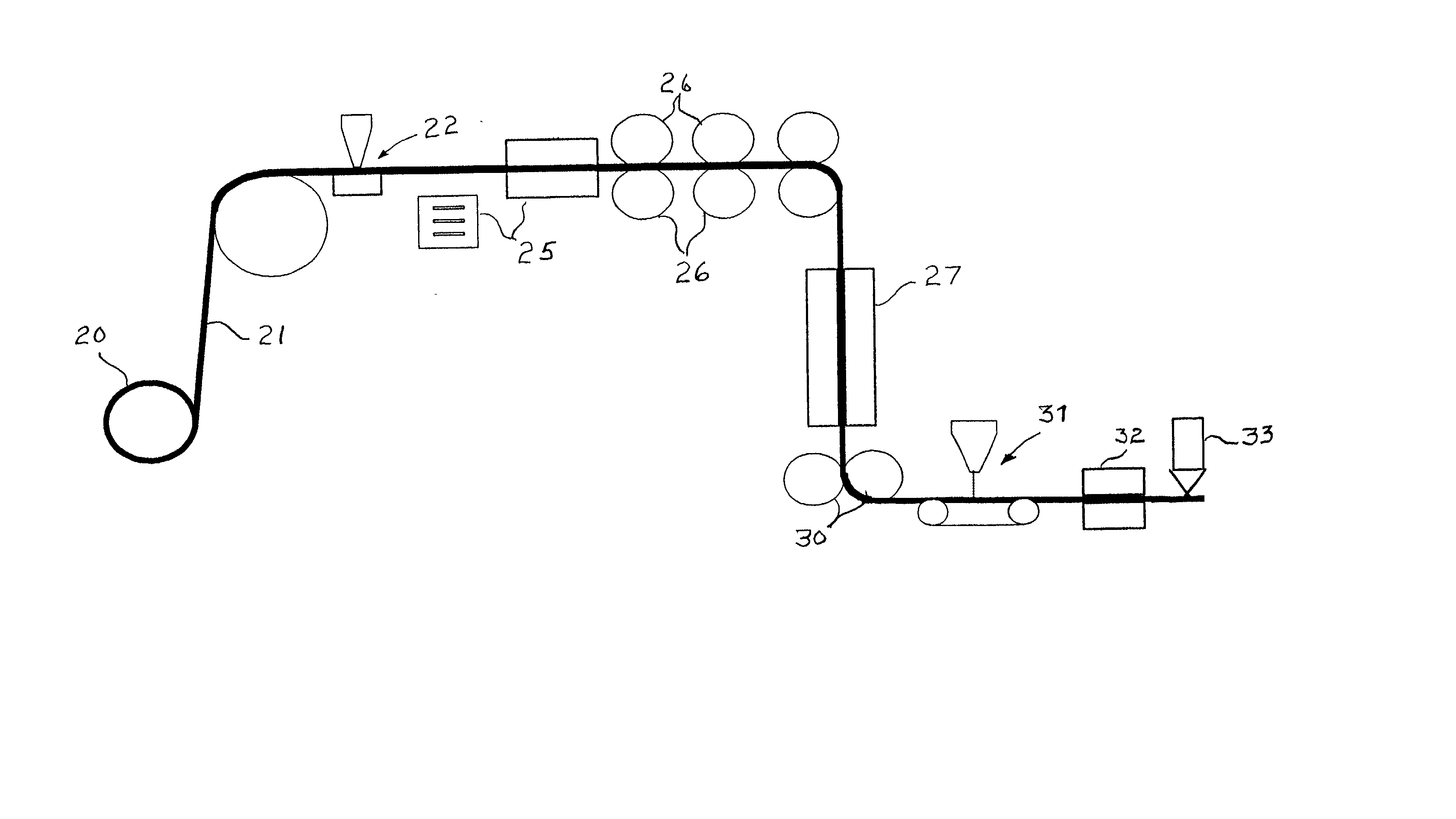
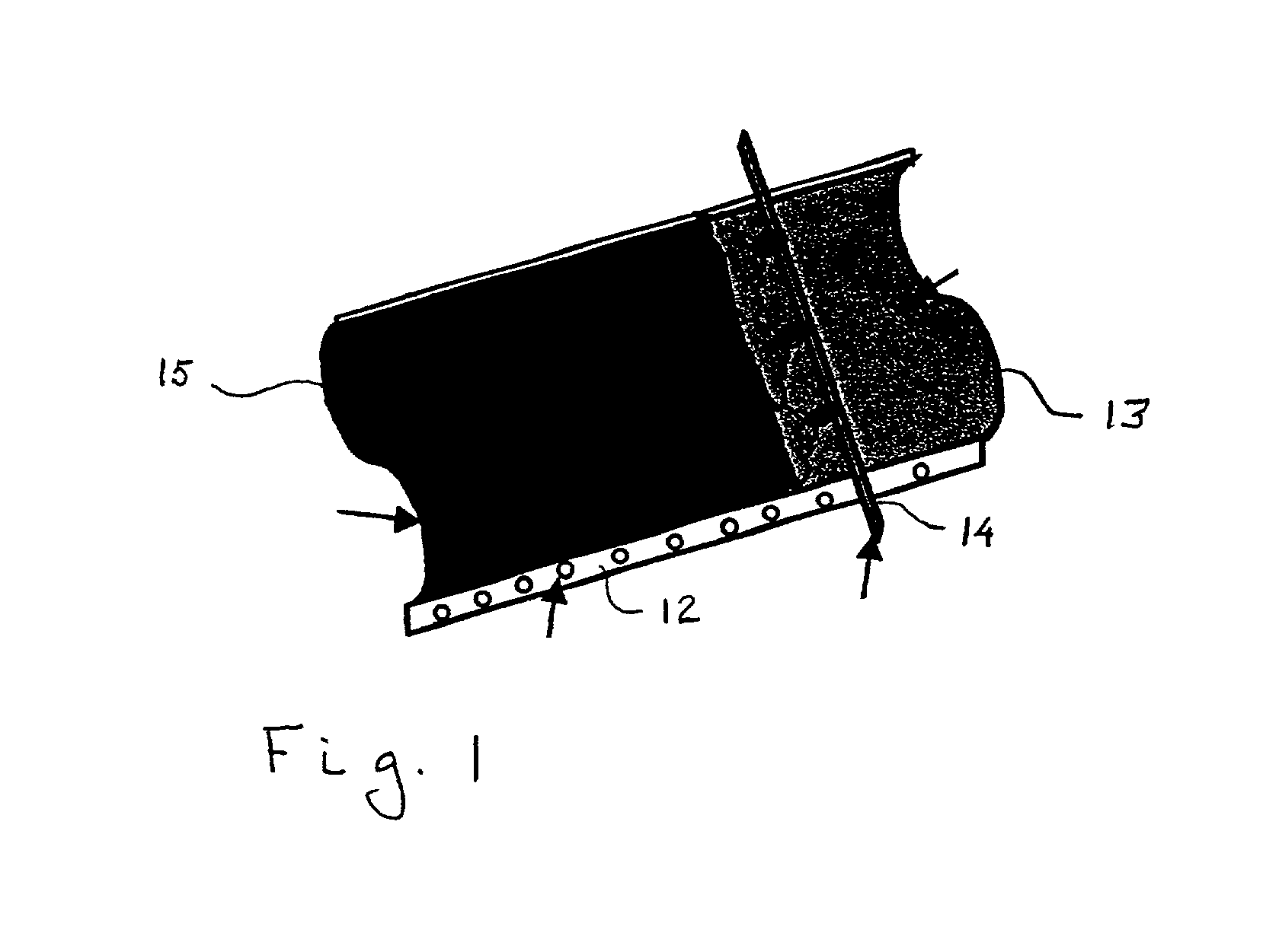
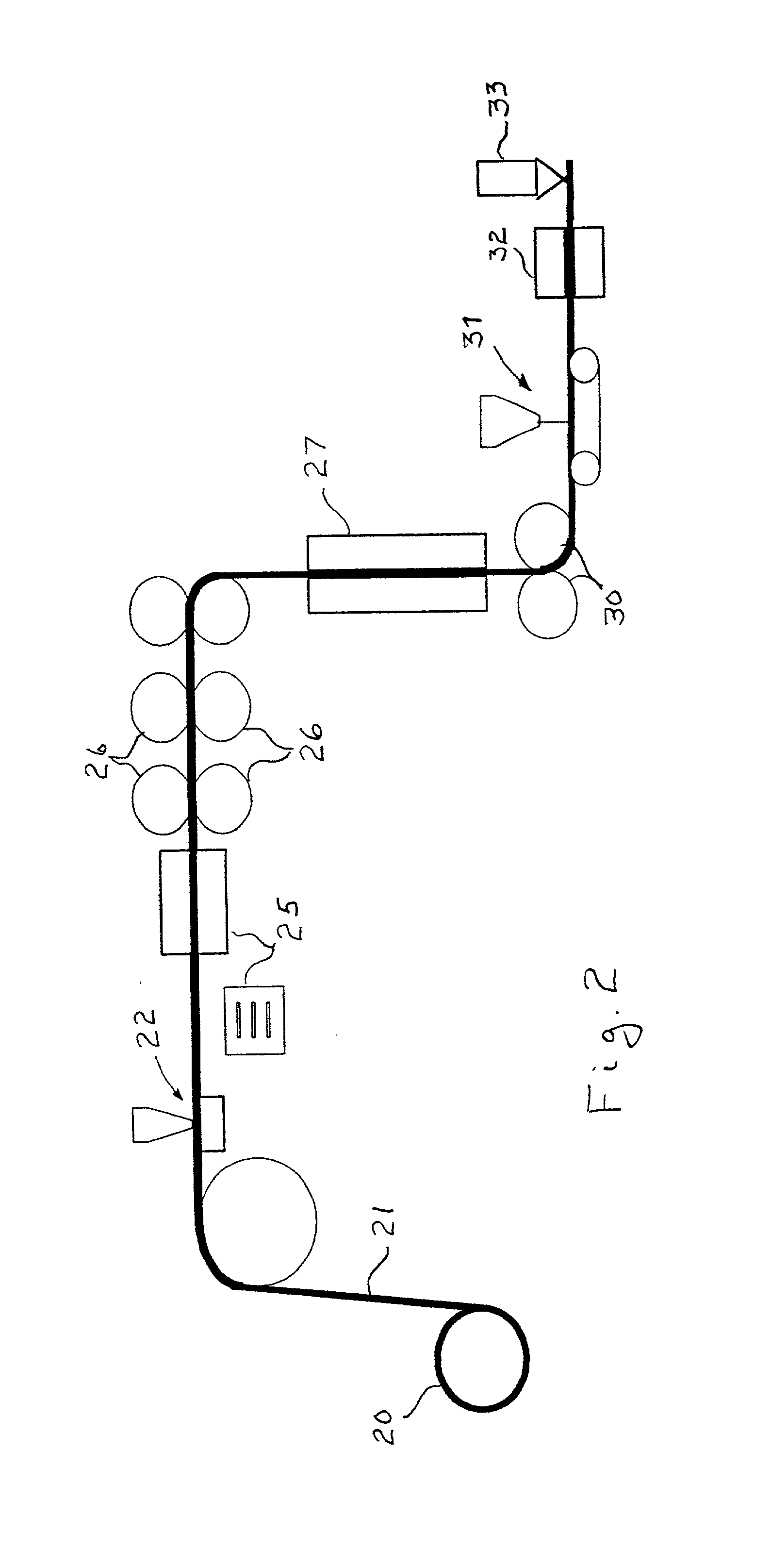
[0030] A gas diffusion electrode is produced in accordance with the method of this invention by mixing a slurry comprising carbon black, at least one alcohol and water with a tetrafluoroethylene emulsion to form a Teflonized carbon black slurry which, in turn, is applied to a non-Teflonized carbon cloth substrate, forming a coated carbon cloth. In accordance with one preferred embodiment, the carbon black slurry is applied to the carbon cloth substrate by tape casting, also known as doctor blading and knife coating. The process utilizes a scraping blade, known as the "doctor" for the removal of excess substances from a moving surface being coated, in the instant case the carbon cloth substrate. The coated carbon cloth is then heated to a temperature suitable for driving off water, preferably about 107.degree. C. to about 110.degree. C., producing a substantially dry coated carbon cloth. The substantially dry coated carbon cloth is then rolled, preferably through two rolls with a cer...


PUM

PropertyMeasurementUnit
temperatureaaaaaaaaaa
pressureaaaaaaaaaa

Abstract

A method for producing a gas diffusion electrode in which a slurry of carbon black, alcohol, water and a tetrafluoroethylene emulsion is applied as a layer a non-Teflonized carbon cloth substrate, which is then heated to remove water. The dried coated carbon cloth is then rolled followed by heating to remove wetting agents present in the tetrafluoroethylene emulsion. The coated carbon cloth is then cooled and rolled again to produce the final end product.

Description

[0001] 1. Field of the Invention[0002] This invention relates to polymer electrolyte membrane fuel cells and methods for producing components thereof. More particularly, this invention relates to a method for producing gas diffusion electrodes and membrane electrode assemblies for polymer electrolyte membrane fuel cells.[0003] 2. Description of Prior Art[0004] A polymer electrolyte membrane fuel cell is an electrochemical device comprising an anode electrode, a cathode electrode and an electrolyte in the form of a thin polymeric membrane disposed between the anode electrode and the cathode electrode. Individual polymer electrolyte membrane fuel cells or fuel cell units are stacked with bipolar separator plates separating the anode electrode of one fuel cell unit from the cathode electrode of an adjacent fuel cell unit to produce polymer electrolyte membrane fuel cell stacks. Conventionally, the electrodes are gas diffusion electrodes that are bonded or applied on either side of the ...

Claims


Application Information

Patent Timeline
Patent Type & Authority Applications(United States)
IPC IPC(8): H01M4/88H01M8/10
CPCH01M4/8807H01M4/8835H01M4/886H01M8/0234H01M8/1004Y02E60/522Y02P70/50Y02E60/50
Inventor FAN, QINBAILE, SIEM
Owner GAS TECH INST
Why Eureka
Try Eureka