Articles Including Expanded Polytetrafluoroethylene Membranes with Serpentine Fibrils and Having a Discontinuous Fluoropolymer Layer Thereon

a technology of expanded polytetrafluoroethylene and serpentine fibrils, which is applied in the field of expanded polytetrafluoroethylene (eptfe) membranes with serpentine fibrils and discontinuous fluoropolymer layers and to materials made therefr, can solve the problems of exceptionally weak membranes in this direction and uniaxial expansion materials that can exhibit high elongation

Active Publication Date: 2013-07-18
WL GORE & ASSOC INC
View PDF5 Cites 46 Cited by
  • Summary
  • Abstract
  • Description
  • Claims
  • Application Information

AI Technical Summary

Benefits of technology

[0015]The present invention is directed to fluoropolymer membranes that exhibit high elongation while substantially retaining the strength properties of the fluoropolymer membrane. Such membranes characteristically possess serpentine fibrils having a width of about 1.0 micron or less.

Problems solved by technology

Uniaxially expanded materials can exhibit high elongation when stressed in the direction orthogonal to the fibrils; however, the membranes are exceptionally weak in this direction.

Method used


Image

  • Articles Including Expanded Polytetrafluoroethylene Membranes with Serpentine Fibrils and Having a Discontinuous Fluoropolymer Layer Thereon
  • Articles Including Expanded Polytetrafluoroethylene Membranes with Serpentine Fibrils and Having a Discontinuous Fluoropolymer Layer Thereon
  • Articles Including Expanded Polytetrafluoroethylene Membranes with Serpentine Fibrils and Having a Discontinuous Fluoropolymer Layer Thereon

Examples


example 1

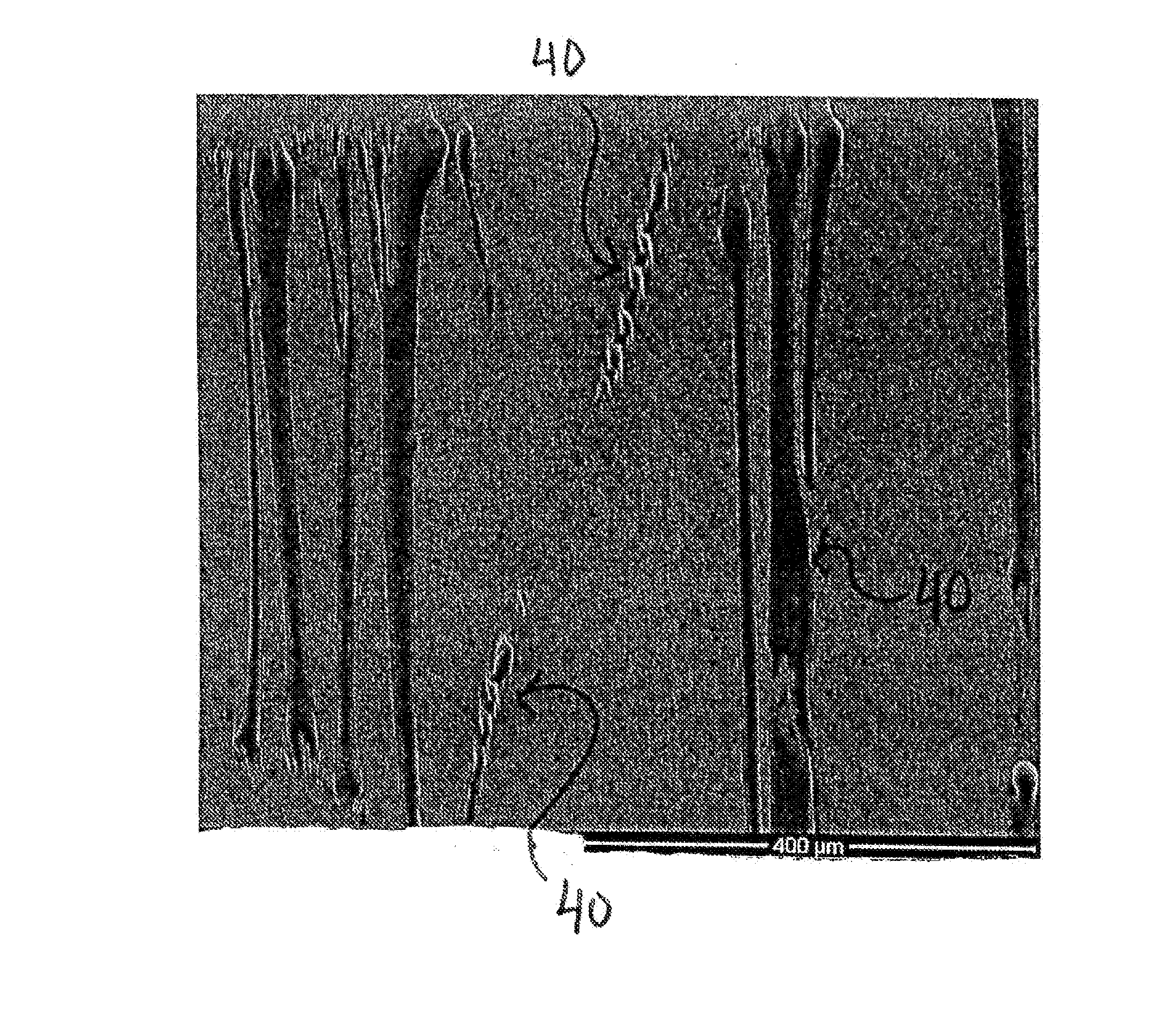
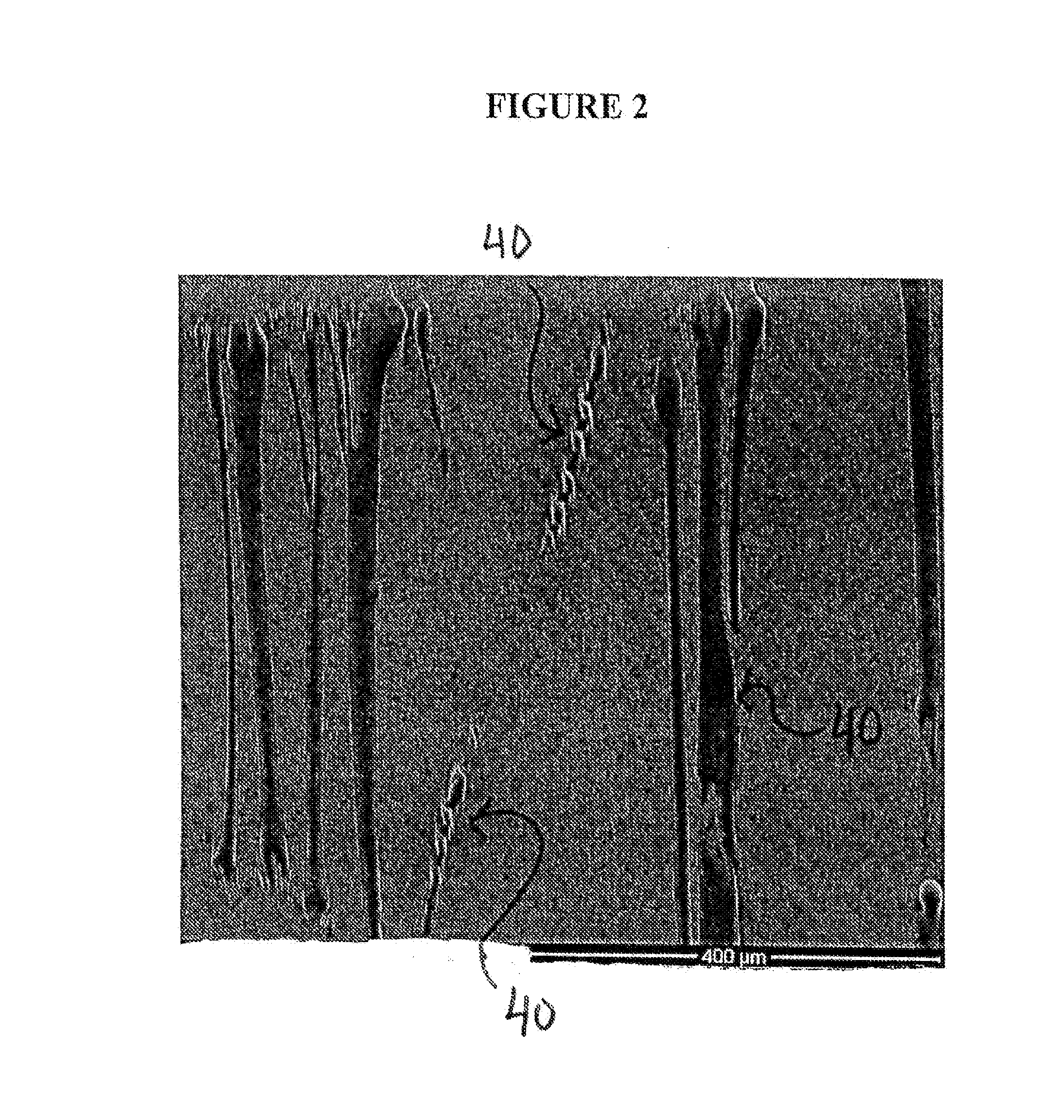
[0056]Expanded Fluoropolymer Membrane with Discontinuous FEP

[0057]Fine powder of PTFE polymer as described and taught in U.S. Pat. No. 6,541,589 was blended with Isopar K (Exxon Mobil Corp., Fairfax, Va.) in the proportion of 0.209 g / g of fine powder. The lubricated powder was compressed into a cylinder to form two pellets that were placed into an oven set at 49° C. for approximately 12 hours. The compressed and heated pellets were ram extruded to produce tape approximately 16.2 cm wide by 0.70 mm thick. The two extruded tapes were then layered and rolled down between compression rolls to a thickness of 0.381 mm. The calendared tape was then transversely stretched to 32 cm (i.e., at a ratio of 2.0:1) and dried at a temperature of approximately 230° C. An approximately 12.5 um thick by approximately 28 cm wide FEP film available from Dupont De Numerous, Inc., (Wilmington, Del.) was obtained. The calendered PTFE tape and the FEP film were laminated together during a longitudinal expan...

example 2

[0060]The retracted membrane of Example 1 was used to create a covered stent device. An 8 mm diameter×6 mm long stainless steel stent (Cordis Palmaz-Schatz Transhepatic Biliary stent, Cat. No. PS5608A, Lot No. R0599853, Cordis Corp., Bridgewater, N.J.) was obtained. The retracted membrane of Example 1 was used to cover the stent as follows. A tube was constructed from a 150 mm wide sample of the membrane. A 4 mm diameter, 150 mm long stainless steel mandrel was obtained. Twelve layers of the 150 mm wide membrane were circumferentially wrapped around the mandrel such that the retracted direction of the membrane was oriented along the circumferential axis of the mandrel. The FEP side of the membrane faced outward. A soldering iron set to approximately 320° C. was used to spot tack the free edge of the film. A 1.3 cm wide slit of an ePTFE film was wrapped on each end of the tube to avoid longitudinal retraction during subsequent heating. The assembly was then placed into an oven set to...


PUM

PropertyMeasurementUnit
widthaaaaaaaaaa
widthaaaaaaaaaa
diameteraaaaaaaaaa

Abstract

Articles comprising an expanded polytetrafluoroethylene membrane having serpentine fibrils and having a discontinuous coating of a fluoropolymer thereon are provided. The fluoropolymer may be located at least partially in the pores of the expanded fluoropolymer membrane. In exemplary embodiments, the fluoropolymer is fluorinated ethylene propylene. The application of a tensile force at least partially straightens the serpentine fibrils, thereby elongating the article. The expanded polytetrafluoroethylene membrane may include a microstructure of substantially only fibrils. The articles can be elongated to a predetermined point at which further elongation is inhibited by a dramatic increase in stiffness. In one embodiment, the articles are used to form a covered stent device that requires little force to distend in the radial direction to a first diameter but is highly resistant to further distension to a second diameter (stop point). A large increase in diameter can advantageously be achieved prior to reaching the stop point.

Description

CROSS REFERENCE TO RELATED APPLICATIONS[0001]This application is a continuation-in-part of U.S. patent application Ser. No. 13 / 351,051 to White, et al. filed on Jan. 16, 2012.FIELD OF THE INVENTION[0002]The present invention relates to expanded polytetrafluoroethylene (ePTFE) membranes having serpentine fibrils and a discontinuous fluoropolymer layer and to materials made therefrom.DEFINITIONS[0003]As used herein, the term “serpentine fibrils” means multiple fibrils that curve or turn one way then another.[0004]As used herein, the term “controlled retraction” refers to causing articles to shorten in length in at least one direction by the application of heat, by wetting with a solvent, or by any other suitable means or combinations thereof in such a way as to inhibit folding, pleating, or wrinkling of the subsequent article visible to the naked eye.[0005]The term “imbibed or imbibing” as used herein is meant to describe any means for at least partially filling at least a portion of ...

Claims


Application Information

Patent Timeline
Patent Type & Authority Applications(United States)
IPC IPC(8): A61F2/07B32B38/18A61F2/82C09D127/18
CPCA61L31/10Y10T428/24802Y10T428/2481A61L31/048A61L31/146A61L31/129Y10T156/1075A61F2002/075F21V33/0076A61F2/07C09D127/18B32B38/1866A61F2/82C08L27/18C08L27/12A61F2240/002B29C65/02B29C66/545B29K2055/00B29K2105/04B29K2105/08B29L2009/00B29L2031/753B32B1/08B32B5/10B32B27/322B32B37/06B32B2305/02B32B2355/00B32B2535/00
Inventor KOVACH, LARRY J.RADSPINNER, RACHEL
Owner WL GORE & ASSOC INC
Why Eureka
Try Eureka