System and method for intelligent wire testing

a technology of intelligent wires and testing methods, applied in automated test systems, testing circuits, instruments, etc., can solve problems such as significant economic losses, configuration control anomalies, and the inability of technicians and engineers to detect all design defects, and achieve the effect of reducing the complexity of resolving latent design defects

Inactive Publication Date: 2002-10-10
GRC INT INC
View PDF0 Cites 45 Cited by
  • Summary
  • Abstract
  • Description
  • Claims
  • Application Information

AI Technical Summary

Problems solved by technology

Even with the benefit of CAD, it is virtually impossible for the technicians and engineers to detect all design defects, configuration control anomalies, and verification omissions that develop during the design process.
In the unfortunate event that a system is manufactured according to a design that contains latent design defects, significant economic losses can accumulate from the need to repeatedly update the manufacturing process, such that newly detected design defects are systematically identified and cured.
Resolving latent design defects can be further complicated if an accurate configuration control of the system has not been maintained.
Another problem with this manual design process is that verification depends greatly upon the prior experience of the personnel verifying the design.
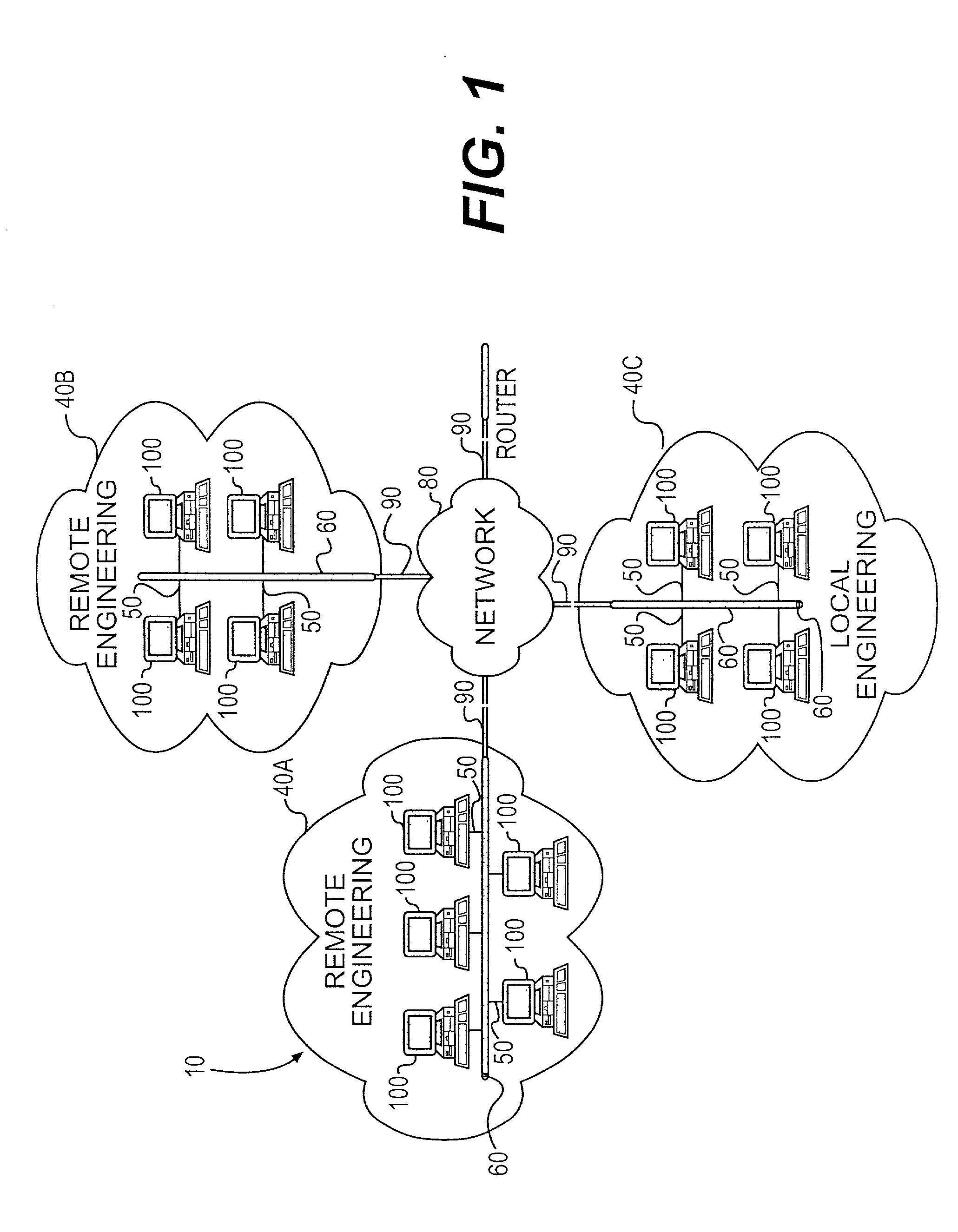
History has shown that there is no easy means of sharing the accumulated experience of one engineer with other engineers, particularly when the knowledge lies in the minds of people located in geographically dispersed areas.
As a result, omissions repeatedly occur, with the incidence of errors late in the process particularly high.
Even when CAD systems were used to verify design, the result was usually insufficient, particularly for modern systems.
More specifically, prior art CAD systems also tend to simply verify the interoperability with respect to physical properties like component weight, size and dimensions because it is difficult to model and verify the effect of other external influences like temperature, humidity and component age.
Prior art CAD systems are also unable to comprehensively verify data obtained through the interaction of components or forces, e.g., the voltage applied to a specific component.
However, it quickly became obvious that the programs tended to be lengthy, complicated and time-consuming to create.
Moreover, the task of writing and supporting testing programs for each of the myriad of ATE platforms was expensive and resource intensive.
Although random and pseudo-random instruction generators can provide a wide range of possible instruction sequences with minimal user input, they do not intuitively understand which instruction sequences are likely to be the most difficult for the microprocessor to handle.
For some designs, such instructions may not test an adequately wide spectrum of instruction sequences.
Thus, they fail to adequately test important aspects of a system's functioning and design.

Method used


Image

  • System and method for intelligent wire testing
  • System and method for intelligent wire testing
  • System and method for intelligent wire testing

Examples


Embodiment Construction

[0036] In the following detailed description of one embodiment, reference is made to the accompanying drawings that form a part thereof, and in which is shown by way of illustration a specific embodiment in which the invention may be practiced. This embodiment is described in sufficient detail to enable those skilled in the art to practice the invention and it is to be understood that other embodiments may be utilized and that structural changes may be made without departing from the scope of the present invention. The following detailed description is, therefore, not to be taken in a limited sense.

[0037] To achieve these and other advantages, and in accordance with the purpose of the invention as embodied and broadly described, the invention provides an object-oriented database model of a physical system for supporting a broad spectrum of user functions including design analysis, operations assessments, real-time maintenance and configuration management. One embodiment of the inven...


PUM


Abstract

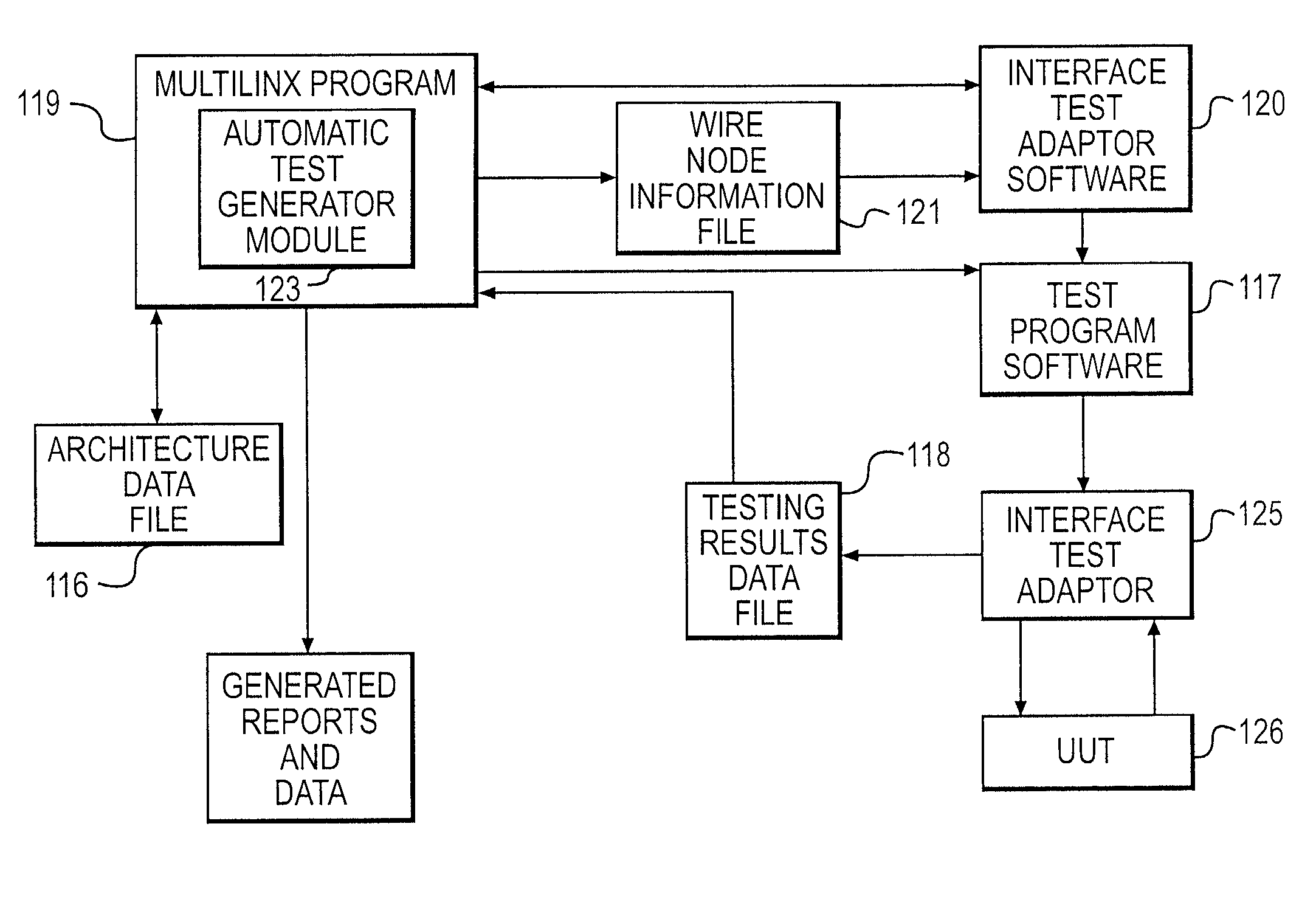
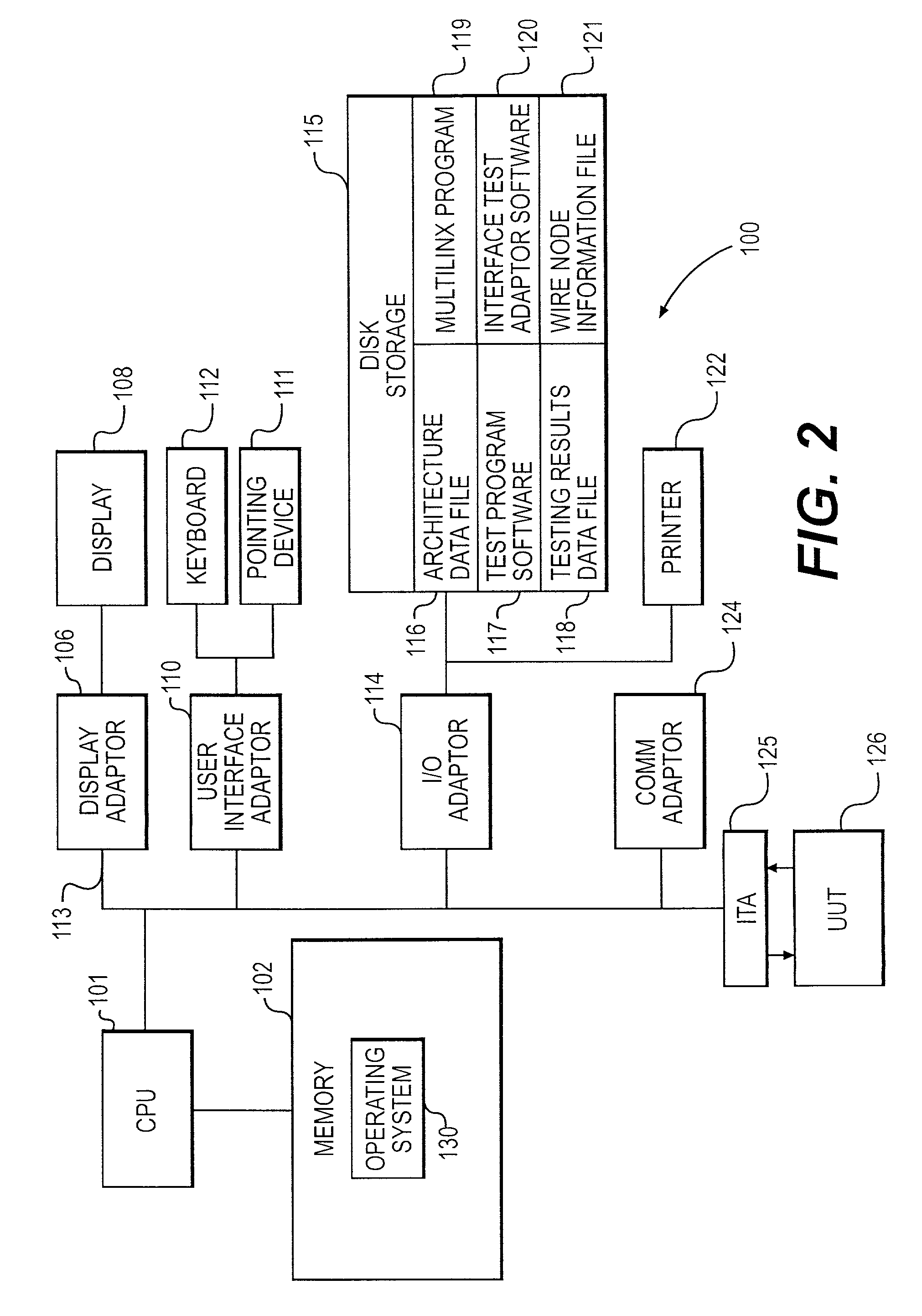
A system and method for providing an intelligent wire testing capability for complex hardware systems. The system is comprised of a software application with a relational database interfacing with an automatic test equipment module. The relational database contains all of a system's architecture information plus all of the text and parametric information associated with the design. During a system test, the subject invention uses the wiring/system architecture as disclosed in the relational database together with an automatically generated test program to identify faults in a unit under test. Using the architecture knowledge, the subject invention is capable of automatically generating a wire harness schematic for printout or display on a CRT. The architecture knowledge also allows a technician to quickly distinguish between a broken wire and an unused pin in a connector. After the test, the observed values are stored in a testing results file for later review and trend analysis. Data from the trend analysis provides the technician with the data necessary to assess the state of the wiring in the UUT. At the completion of testing, the testing results file stays with the UUT thereby ensuring access to a complete testing history of the UUT at any time.

Description

[0001] The invention relates generally to computer systems and more particularly, to a computer system tool for testing wiring, components and interfaces in a complex system.DESCRIPTION OF THE RELATED ART[0002] System engineering is the technical discipline concerned with the conceptualization, design, construction and testing of complex systems. A comprehensive and well-structured approach to system engineering, facilitates the swift, cost-effective progression of new technologies from raw concept to end product.[0003] In the past, system engineering meant that a team of engineers and designers worked together in a labor-intensive, paper laden process throughout the system development life-cycle to conceive and field complex engineering systems. By way of background, the system development life-cycle consists of six stages, the first being concept definition, in which the goals of the project are broadly stated. The output of the concept definition stage become the genesis for the ...

Claims


Application Information

Patent Timeline
Patent Type & Authority Applications(United States)
IPC IPC(8): G01R31/28G01R31/3183
CPCG01R31/318307G01R31/2834
Inventor BARACAT, WILLIAMBROWN, MARKBARTLEBAUGH, BRIANFERRETT, LISALIU, FONDA FANG
Owner GRC INT INC
Why Eureka
Try Eureka