
Identification tag utilizing charge pumps for voltage supply generation and data recovery

a technology of identification tags and charge pumps, applied in the direction of near-field systems using receivers, instruments, burglar alarm mechanical actuation, etc., can solve the problems of large power consumption of available tags, inefficient power schemes of tag power schemes, and large cost of current available tags

Inactive Publication Date: 2002-10-17
SYMBOL TECH LLC
View PDF16 Cites 39 Cited by
  • Summary
  • Abstract
  • Description
  • Claims
  • Application Information

AI Technical Summary

Problems solved by technology

For instance, currently available tags are relatively expensive.
Furthermore, currently available tags consume large amounts of power.
Currently available tag power schemes, which include individually tag-included batteries, are inefficient and expensive.
These inefficient power schemes also lead to reduced ranges over which readers may communicate with tags in a wireless fashion.
Still further, currently available readers and tags use inefficient interrogation protocols.
These inefficient protocols slow the rate at which a large number of tags may be interrogated.
However, this may also introduce a burden on the implementation to add functionality, memory, processing power, etc., in order to present information to the highest OSI model layers.
This may result in an orientation sensitivity for a tag antenna with respect to a reader antenna that can greatly reduce the operational distance for a non-optimum orientation.
This is not desirable to the majority of markets looking for RFID products.
Again, a similar problem exists in that the wider frequency agility of a given antenna design will reduce the gain, or collected energy of a single antenna.
Wafer fabrication process variations may cause performance differences between chips.
These high temperatures can cause standard polymers to degrade quickly as well as become very unstable to work with.
Non-conductive oxides are detrimental to RF (UHF) performance, as they can significantly cause an antenna to detune.
This pattern of bits that were received may actually have been noise or were noise affected.
This assumption has a chance of error, of course, and is determined statistically upon the randomness of noise.
For example, a single-bit pattern may be considered to have a 1 in 2 chance of being generated by noise, which is not generally acceptable in industry.
However, this process may be more affected by RF noise in the environment.
This may occur in a noisy transmission environment.

Method used


Image

  • Identification tag utilizing charge pumps for voltage supply generation and data recovery
  • Identification tag utilizing charge pumps for voltage supply generation and data recovery
  • Identification tag utilizing charge pumps for voltage supply generation and data recovery

Examples


Embodiment Construction

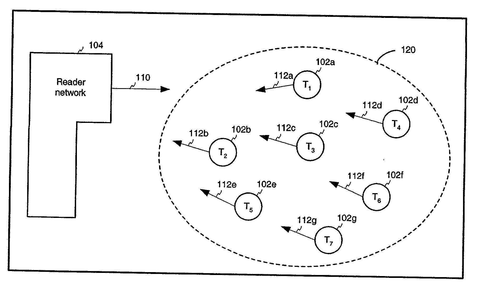
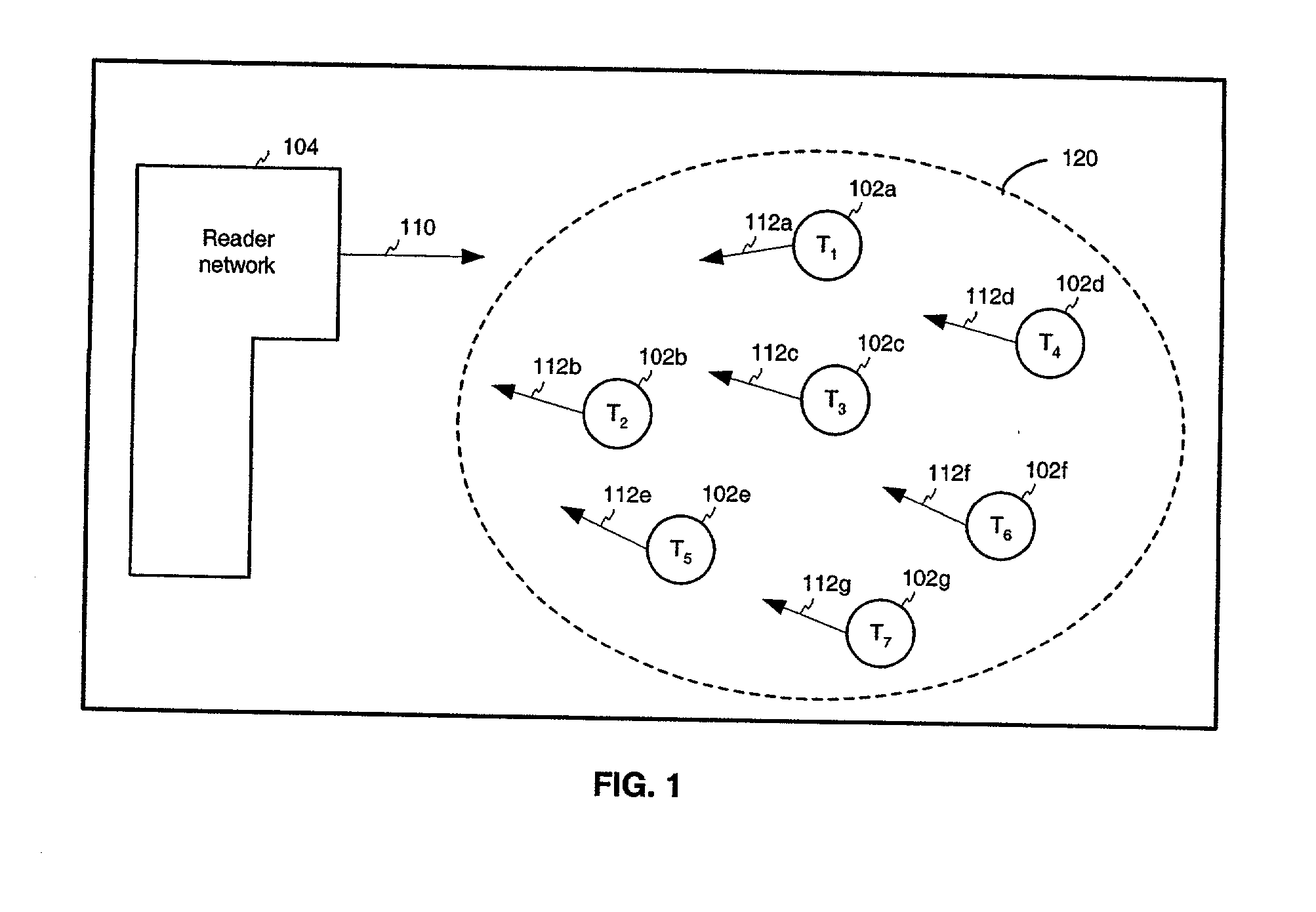
[0315] FIG. 17A shows a flowchart illustrating operation of a tag 102 in superposition state 1210. As shown in FIG. 17A, operation begins with step 1702. In step 1702, tag 102 is in dormant state 1202.

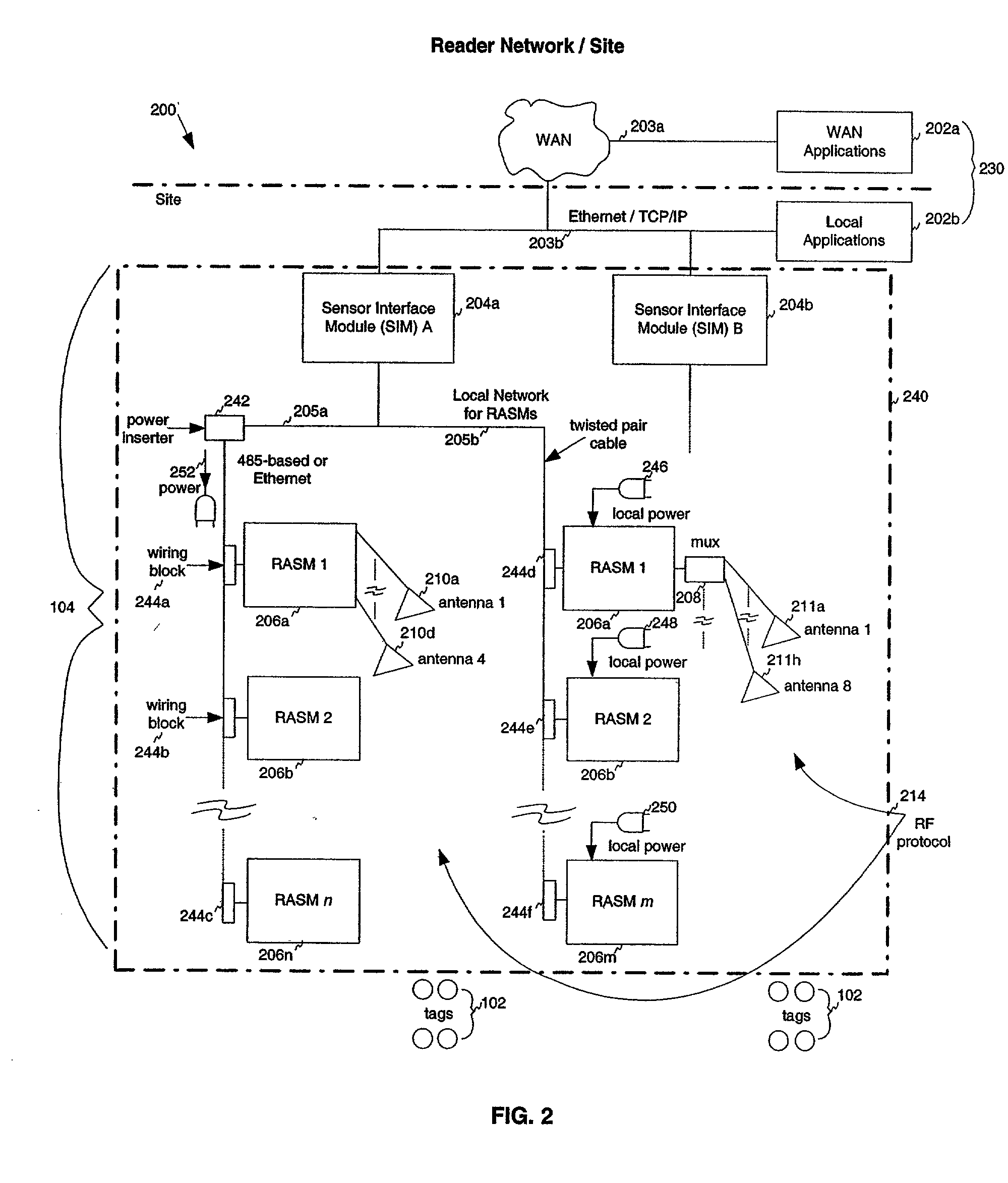
[0316] In step 1704, tag 102 receives a master reset signal from reader network 104. Upon receipt of this signal, tag 102 transitions from dormant state 1202 to calibration state 1204.

[0317] In step 1706, tag 102 is synchronized with reader network 104. Accordingly, oscillator calibration and data calibration procedures occur, that are further described below. After tag 102 becomes synchronized with reader network 104, it enters command state 1206.

[0318] In step 1708, tag 102 receives a command from reader network 104 that causes tag 102 to transition to superposition state 1210. As described above, the command may be a one or more bits, such as a single bit logical "1" symbol 402.

[0319] In step 1710, tag 102 designates an initial bit of its identification number for transmission as a ...


PUM


Abstract

An identification (ID) tag includes a substrate having an input capable of receiving a high frequency signal. For instance, the high frequency signal can be a radio frequency (RF) signal that is generated as part of a radio frequency (RF) ID system. A first charge pump is coupled to the input and is configured to convert the high frequency signal to a substantially direct current (DC) voltage. A data recovery circuit is coupled to the input and is capable of recovering data from the high frequency signal. A back scatter switch is coupled to the input and is capable of modifying an impedance of the input, responsive to a control signal. A state machine is disposed on the substrate and is responsive to the data recovered by the second charge pump, where the state machine is capable of generating the control signal for the back scatter switch in response to the data. The DC voltage from the first charge pump is capable of providing a voltage supply for at least one of the data recovery circuit, the back scatter switch, and the state machine. The data recovery circuit includes a second charge pump that is capable of operating on the high frequency signal simultaneously with the first charge pump. In other words, the first charge pump can generate the supply voltage for the ID tag from the high frequency signal, while the second charge pump simultaneously retrieves the data from the high frequency signal. The first charge pump also includes a means for limiting the amplitude of the DC voltage by reducing the charge pump efficiency, once a threshold voltage is reached.

Description

[0001] This application claims the benefit of U.S. Provisional Application No. 60 / 267,713, filed Feb. 12, 2001, which is herein incorporated by reference in its entirety.[0002] 1. Field of the Invention[0003] The present invention relates generally to radio frequency identification (RFID) tags.[0004] 2. Description of the Related Art[0005] Many product-related and service-related industries entail the use and / or sale of large numbers of useful items. In such industries, it may be advantageous to have the ability to monitor the items that are located within a particular range. For example, within a particular store, it may be desirable to determine the presence of inventory items located on the shelf, and that are otherwise located in the store.[0006] A device known as an RFID "tag" may be affixed to each item that is to be monitored. The presence of a tag, and therefore the presence of the item to which the tag is affixed, may be checked and monitored by devices known as "readers." ...

Claims


Application Information

Patent Timeline
IPC IPC(8): G06K7/00G06K17/00G06K19/07G11C5/14H04B1/59H04B5/02H04L7/033
CPCG06K7/0008G06K7/10039G06K7/10069G06K7/10108G06K7/10356G06K17/00H04L7/0331G06K19/0723G06K19/07749G06K19/07767G08B13/2485G11C5/142G06K19/0713
Inventor SHANKS, WAYNE E.BANDY, WILLIAM R.ARNESON, MICHAEL R.POWELL, KEVIN J.
Owner SYMBOL TECH LLC
Learn More