First Embodiment
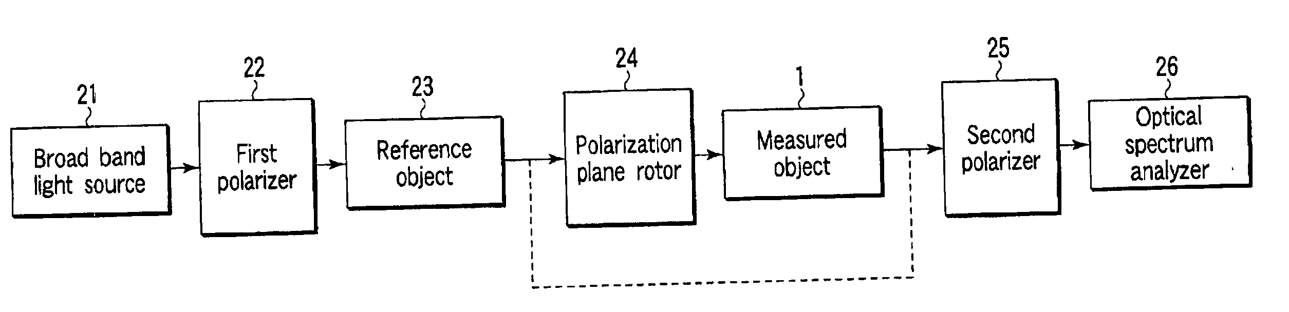
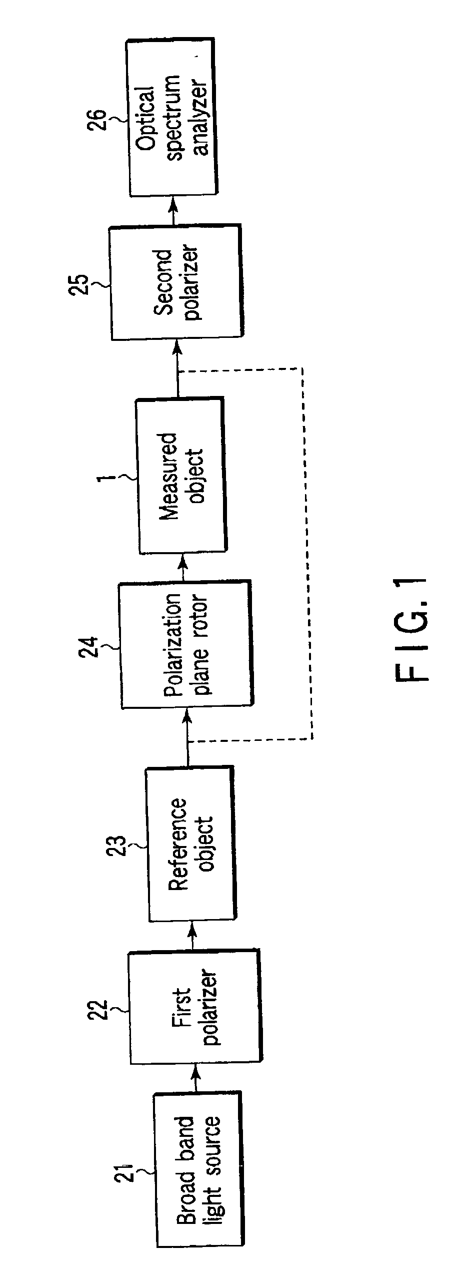
[0089] FIG. 1 is a block diagram that explains a polarization mode dispersion measuring method and a structure of a polarization mode dispersion measuring system for executing this method according to a first embodiment of the present invention.
[0090] In FIG. 1, a broad band light source 21 is constructed of a white-color lamp, an SLD (super-luminescence diode) and the like, and has a substantially uniform spectrum in a wavelength area of a light handled by a measured object 1.
[0091] A light emitted from this broad band light source 21 is incident to a first polarizer 22.
[0092] This first polarizer 22 extracts a linearly polarized beam having a constant polarization direction from the light emitted from the broad band light source 21, and makes the extracted linearly polarized beam incident to one side of a reference object 23.
[0093] The reference object 23 has a PMD value (a differential group delay time) larger than the measured object 1, and for example, an optical fiber (called a PANDA fiber) having a predetermined length manufactured to have an intentionally large difference in refractive indexes due to polarization directions is used.
[0094] On the other end side of this reference object 23, a polarization plane rotor 24 is provided.
[0095] This polarization plane rotor 24 rotates a polarization plane of a light emitted from the reference object 23 by an optional angle, and makes the light of which polarization plane has been rotated incident to one end side of the measured object 1.
[0096] A light emitted from the other end side of this measured object 1 is made incident to a second polarizer 25.
[0097] This second polarizer 25 extracts a linearly polarized beam having a constant polarization direction from the light emitted from the measured object 1, and outputs this light to an optical spectrum analyzer 26.
[0098] This optical spectrum analyzer 26 displays a spectrum of the light emitted from the second polarizer 25 on a screen.
[0099] Then, in this measuring system, as described previously, a PMD value P (a differential group delay time .DELTA..tau.) is calculated by the following equation (1), using a first peak wavelength .lambda.1 and a last peak wavelength .lambda.2, based on the assumption that a wavelength distance between adjacent peaks (or between adjacent bottoms) of this spectrum waveform shown in the optical spectrum analyzer 26 is expressed as a phase difference 2.pi.:
P=k(n-1).multidot..lambda.1.multidot..lambda.2/(C-.DELTA..lambda.) (1)
[0100] where, k represents a mode coupling coefficient, C represents an optical speed, n represents a number of peaks, and .DELTA..lambda.=.lambda.2-.lambda.1.
[0101] The mode coupling coefficient k is a value equal to or lower than 1 that is determined according to an inter-mode coupling status between the X-axis component and the Y-axis component of the light transmitted through the measured object 1. When the optical path length is not very long, it is possible to set as k=1.
[0102] As explained above, according to the system having the reference object 23 and the polarization plane rotor 24 inserted into between the first polarizer 22 and the one end side of the measured object 1, a polarization mode dispersion larger than the PMD value of the measured object 1 is applied to the linearly polarized beam extracted by the first polarizer 22.
[0103] Then, the polarization plane of the light applied with this polarization mode dispersion is rotated by the polarization plane rotor 24, and the light of which polarization plane has been rotated is made incident to the measured object 1.
[0104] Therefore, the polarization direction of the light incident to the measured object 1 changes based on the rotation of the polarization plane effected by the polarization plane rotor 24, and the spectrum displayed on the optical spectrum analyzer 26 also changes accordingly.
[0105] Then, the PMD value calculated based on the spectrum displayed on the optical spectrum analyzer 26 also changes.
[0106] In this case, assume that the PMD value of the polarization plane rotor 24 is negligibly small. Then, when the rotation angle of the polarization plane rotor 24 has been set such that the direction of a change in the phase of the light due to the reference object 23 and a direction of a change in the phase due to the measured object 1 coincide with each other, the PMD value obtained from the spectrum displayed on the optical spectrum analyzer 26 becomes a maximum Pmax.
[0107] This maximum PMD value corresponds to a sum of the PMD value of the reference object 23 and the PMD value of the measured object 1.
[0108] This maximum value Pmax is obtained by obtaining .lambda.1, .lambda.2, n, and .DELTA..lambda. from the spectrum distribution displayed on the optical spectrum analyzer when the above conditions have been set, and by substituting these values and a known optical speed C into the above equation (1).
[0109] Further, in obtaining .lambda.1 and .lambda.2, it has been structured such that a user attaches a marker to two adjacent peak values so that the wavelength at this time is counted and this value is output.
[0110] Further, when the rotation angle of the polarization plane rotor 24 has been set such that the direction of a change in the phase of the light due to the reference object 23 and a direction of a change in the phase due to the measured object 1 become opposite from each other, the PMD value obtained from the spectrum displayed on the optical spectrum analyzer 26 becomes a minimum Pmin.
[0111] This minimum PMD value corresponds to a value obtained by subtracting the PMD value of the measured object 1 from the PMD value of the reference object 23.
[0112] This minimum value Pmin is obtained by obtaining .lambda.1, .lambda.2, n, and .DELTA..lambda. from the spectrum distribution displayed on the optical spectrum analyzer when the above conditions have been set, and by substituting these values and a known optical speed C into the above equation (1).
[0113] Therefore, when the maximum PMD value or the minimum PMD value is obtained by rotating the polarization plane rotor 24, it is possible to obtain the PMD value of the measured object 1.
[0114] Namely, the PMD value of the reference object 23 is expressed as Pr, the PMD value of the measured object 1 is expressed as Px, and the maximum PMD value obtained by rotating the polarization plane rotor 24 is expressed as Pmax. Then,
Pmax=Pr+Px
[0115] is obtained, and when the PMD value Pr of the reference object 23 has already been known, it is possible to obtain the PMD value Px of the measured object 1 by calculating
Px=Pmax-Pr (2).
[0116] In this case, as shown in a flowchart of FIG. 2, first, the PMD value Pr of the reference object 23 is obtained, by connecting the reference object 23 to between the first polarizer 22 and the second polarizer 25 (steps ST1, ST2).
[0117] Next, the maximum PMD value Pmax is obtained, by inserting the polarization plane rotor 24 and the measured object 1 into between the reference object 23 and the second polarizer 25, and by rotating the polarization plane rotor 24 (steps ST3, ST4).
[0118] Next, the PMD value Px of the measured object 1 is obtained, by calculating the difference of the above equation (2) (steps ST3, ST4).
[0119] Further, Pmin=Pr-Px, when the minimum PMD value obtained by rotating the polarization plane rotor 24 is expressed as Pmin, and when the PMD value Pr of the reference object 23 has already been known, it is possible to obtain the PMD value Px of the measured object 1, by calculating
Px=Pr-Pmin (3).
[0120] In this case, as shown in a flowchart in FIG. 3, first, the PMD value Pr of the reference object 23 is obtained, by connecting the reference object 23 to between the first polarizer 22 and the second polarizer 25 (steps ST11, ST12).
[0121] Next, the minimum PMD value Pmin is obtained by inserting the polarization plane rotor 24 and the measured object 1 into between the reference object 23 and the second polarizer 25, and by rotating the polarization plane rotor 24 (steps ST13, ST14).
[0122] Next, the PMD value Px of the measured object 1 is obtained by calculating the difference of the above equation (3).
[0123] Further, from the above equations (2) and (3),
Pmax-Pmin=2Px,
[0124] and, therefore, it is possible to obtain the PMD value Px of the measured object 1, by calculating
Px=(Pmax-Pmin)/2 (4).
[0125] In this case, as shown in a flowchart in FIG. 4, first, the reference object 23, the polarization plane rotor 24 and the measured object 1 are connected to between the first polarizer 22 and the second polarizer 25 (step ST21).
[0126] Next, the maximum PMD value Pmax and the minimum PMD value Pmin are obtained by rotating the polarization plane rotor 24 (steps ST22, ST23).
[0127] Next, the PMD value Px of the measured object 1 is obtained by calculating the above equation (4) (step ST24).
[0128] According to this method, as it is not necessary to obtain the PMD value Pr of the reference object 23, it is possible to obtain the PMD value Px of the measured object 1 by simpler processing.
[0129] A theoretical measurement limit of the PMD value Px of the measured object 1 according to the above measuring method becomes limitless, based on the condition that it is smaller than the PMD value Pr of the reference object 23.
[0130] In other words, a lower limit L of the PMD value that can be obtained from the spectrum of the optical spectrum analyzer 26 in this system is about 50.times.10.sup.-12 (second) as described above. Therefore, the minimum PMD value Pmin that can be obtained by the measurement is a value equal to or more than this lower limit L.
[0131] However, as this minimum PMD value Pmin is equal to Pr-Px, it is necessary that Pr-Px becomes equal to or more than the lower limit L.
[0132] This condition does not limit the lower value of the PMD value Px of the measured object 1.
[0133] For example, even when the PMD value Px is 5.times.10.sup.-12 (second) smaller than the lower limit L, the PMD value Pmin becomes equal to or more than the lower limit value L, when the PMD value Pr of the reference object 23 is larger than 55.times.10.sup.-12 (second).
[0134] Accordingly, there is no theoretical measurement limit of the PMD value Px of the measured object 1, and it is possible to measure accurately the measured object 1 of the PMD value smaller than the measurement limit L of the conventional measuring system.
[0135] As explained above, according to the polarization mode dispersion measuring method of the present embodiment, a polarization mode dispersion larger than a value of the polarization mode dispersion of the measured object 1 is applied to a linearly polarized beam extracted from the broad band light; the light applied with this polarization mode dispersion is incident to one end side of the measured object 1 while rotating the polarization plane of this light, and a value of the polarization mode dispersion is obtained from the spectrum of the linearly polarized beam included in the light emitted from the other end side of the measured object 1; and 1/2 of a difference between the maximum polarization mode dispersion value Pmax and the minimum polarization mode dispersion value Pmin obtained by rotating the polarization plane, or a difference between the maximum polarization mode dispersion value Pmax and the polarization mode dispersion value Pr of the reference object 23, or a difference between the minimum polarization mode dispersion value Pmin and the polarization mode dispersion value Pr of the reference object 23, is calculated as the polarization mode dispersion value Px of the measured object 1.
[0136] Therefore, according to the polarization mode dispersion measuring method of the present embodiment, it is possible to accurately measure the measured object 1 of a PMD value substantially smaller than the measurement limit of the conventional system.
[0137] Further, according to the polarization mode dispersion measuring system of the present embodiment, in the polarization mode dispersion measuring system that makes a linearly polarized beam extracted by the first polarizer 22 from a light emitted from the broad band light source 21 incident to one end side of the measured object 1, detects by the optical spectrum analyzer 26 the spectrum of the linearly polarized beam extracted by the second polarizer 25 from the light emitted from the other end side of the measured object 1, and obtains a value of the polarization mode dispersion of the measured object 1 based on the detected spectrum, there are provided the reference object 23 that has a polarization mode dispersion value larger than the polarization mode dispersion value of the measured object 1, between the first polarizer 22 and the one end side of the measured object 1, receives at one end side the linearly polarized beam extracted by the first polarizer 22, and emits the linearly polarized beam from the other end side, and the polarization plane rotor 24 that optionally rotates the polarization plane of the light emitted from the reference object 23, and makes this light incident to the one end side of the measured object 1.
[0138] Therefore, according to the polarization mode dispersion measuring system of the present embodiment, it is possible to obtain with the polarization plane rotor 24 the maximum PMD value that corresponds to a sum of the PMD value of the reference object 23 and the PMD value of the measured object 1, and the minimum PMD value that corresponds to a value obtained by subtracting the PMD value of the measured object 1 from the PMD value of the reference object 23, and from these values, it is possible to accurately obtain a PMD value of the measured object 1 even when this PMD value is a small value.