Method for detecting and correcting non-linearities in a microwave radar system

Inactive Publication Date: 2002-10-31
ROBERT BOSCH GMBH
View PDF0 Cites 5 Cited by
  • Summary
  • Abstract
  • Description
  • Claims
  • Application Information

AI Technical Summary

Benefits of technology

0014] The invention furthermore makes it possible, in advantageous fashion, for the voltage/frequency characteristic of the module for generating the function for frequency modulation to be updated, in consideration of the reference signal, during the aforementioned time window; and for the updated voltage/frequency characteristic to be employed during operation of the microwave radar system, outside the time window, for frequency modulation of the transmitting oscillator. By varying the test trigger voltage in successive time windows it is thus possible, in simple fashion, to ascertain and update the entire voltage/frequency characteristic if it has changed, for example, as a result of temperature influences. The characteristic thus determined can then be taken into account in generating a modulation ramp for the trigger voltage profile in normal operation, the result being that a linear frequency ramp is emitted by the microwave radar.
0015] The method according to the pre

Problems solved by technology

These frequency control systems and the circuit components belonging thereto must be continuously monitored as to functionality during operation, since any faulty behavior within the frequency control circuit results in modulation with insufficiently linear frequency ra

Method used


Image

  • Method for detecting and correcting non-linearities in a microwave radar system
  • Method for detecting and correcting non-linearities in a microwave radar system
  • Method for detecting and correcting non-linearities in a microwave radar system

Examples


Embodiment Construction

[OF THE EXEMPLARY EMBODIMENT]

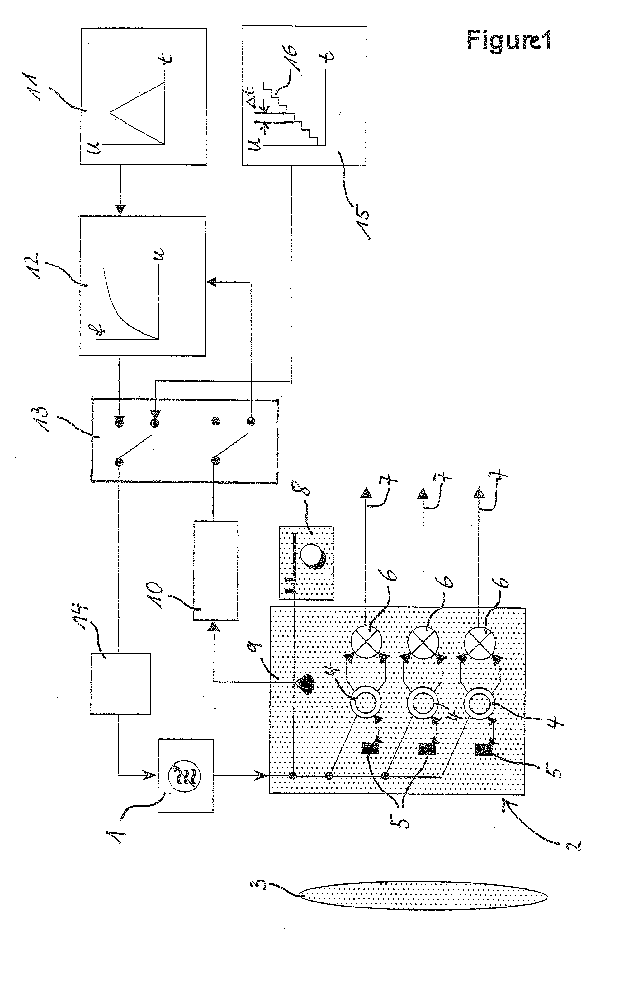
[0020] FIG. 1 depicts a block diagram with the elements of an FMCW microwave radar system that are [essential] important for the present invention. A voltage-controlled transmitting oscillator (Gunn VCO), for example in the 76.5-GHz frequency range, is present; its output signal is sent to a transmit / receive module 2. This transmit / receive module 2, with a lens 3 placed in front of it, can be, for example, a constituent of a radar sensor on a motor vehicle, with which the distance to an object, for example a preceding vehicle, is to be ascertained.

[0021] In transmit / receive module 2, the transmitted signal is sent via coupling modules 4 to (in this case) three antennas 5 for lateral detection of an object, and the received signal reflected from the object is mixed in respective mixers 6 with the transmitted signal f.sub.GUNN; the mixed signal at outputs 7 is employed, in the manner already mentioned [in the introductory portion of the specification] abov...


PUM


Abstract

A method is proposed for detecting and compensating for nonlinearities in a microwave radar system, in which a transmitted signal frequency-modulated according to a defined function is generated with a transmitting oscillator (1), and from the mixing of the transmitted signal with a received signal reflected from an object, a distance of the microwave radar system from the object is ascertained. In defined time windows (DELTAt), instead of a trigger voltage effecting frequency modulation, a defined constant test trigger voltage is switched to the transmitting oscillator (1); a reference signal ascertained in the context of the respective constant test trigger voltage, which signal corresponds to a frequency value of the transmitting oscillator (1), is employed to correct the characteristic for the frequency modulation and thus to compensate for nonlinearities.

Description

BACKGROUND INFORMATION OF THE INVENTION[0001] The invention relates to a method for detecting and correcting nonlinearities in a microwave radar system, as defined in the preamble of the principal claim.] It is known, for example from German Patent No. 197 13 967 [A1], that in a system for distance measurement in the vicinity of motor vehicles, a so-called frequency-modulated continuous wave (FMCW) microwave radar sensor is present. This radar sensor includes as essential elements a transmitting oscillator, a mixer, and an antenna system for radiating and receiving the radar beams reflected from an object. The transmitted signal is, for example, frequency-modulated with a defined ramp function, so that on the basis of the transit time of the received reflected signals, a frequency of the transmitted signal modified in the interim by the modulation ramp is present; and that frequency difference is a direct indication of the distance measurement.[0002] The linearity of the aforementio...

Claims


Application Information

Patent Timeline
IPC IPC(8): G01S7/35G01S7/40G01S13/34G01S13/931H03C3/08
CPCG01S7/032G01S7/352H03C3/08G01S13/34G01S13/931G01S7/4008
Inventor WINTER, KLAUSWINNER, HERMANN
Owner ROBERT BOSCH GMBH
Why Eureka
Try Eureka