
Method for introducing and removing workpieces into or from a surface treatment area, a surface treatment device and an arrangement for surface treatment

Inactive Publication Date: 2002-11-07
ABB FLAEKT AB
View PDF0 Cites 17 Cited by
  • Summary
  • Abstract
  • Description
  • Claims
  • Application Information

AI Technical Summary

Benefits of technology

[0008] In addition to the known advantages of a method according to the initially cited publication of the relevant category, the following advantages will result. As mentioned above, treatment areas having a reduced height (or depth) may be used which are easier to manufacture and to transport. In particular treatment baths may be produced at reduced cost. In addition to this, due to the low bath level, the pressure load in treatment baths is reduced so that these treatment baths may be designed for lower loads. This leads to reduced material cost and the production measures are more cost-advantageous. Due to the lower bath level at unchanged length and width of the treatment basin, the bath volume necessary to allow the workpiece to be completely dipped into the bath is reduced and less bath medium is required. As a result, this allows a considerable reduction of the necessary bath medium volume for greater systems. In addition to this, a cost-advantageous treatment of the workpieces becomes therewith possible. Corresponding to the reduced amount of bath medium, smaller counter-containers may be used particularly in pre-treatment systems and catalytic dip painting, which is again cost-saving. Due to the reduced bath volume less energy is required for transfer-pumping and heating the bath media. This represents also a considerable contribution to cost-reduction. The apparatus may be used as a substituent for the existing pendulum-type or overhead materials-handling technology. Already existing treatment baths or treatment tanks as well as the corresponding process technology may be further used. Previous systems according to the prior art initially mentioned may correspondingly be modified without greater expenditure.
[0012] As is the case with the prior art, the rotational movement is in particular guided at all times in a controlled manner. This means that, the workpiece will not "fall down" or turn further around the rotational axle in an uncontrolled manner. It was established that it is extremely advantageous that the rotational axle follows a horizontal path distance during lifting which is identical with the horizontally travelled path distance during lowering. This allows the optimal use of the length of a treatment area. It is however, under certain circumstances, expedient that the rotational axle travels a shorter horizontal path distance during lifting as is the case during lowering, or vice versa. The latter means that the rotational axle moves a longer horizontal path distance during lifting than during the lowering operation.
[0018] If designed optimally, the guide elements are made in the form of rails and guide the end pieces of a rotational axle, so that the rotational axle performs a translational movement therein and can be moved according to a horizontal alignment. Such a design is technically simple, cost-advantagous, and in addition, robust.
[0019] As was the case with the prior art, in the present invention it is also preferred to continuously, translationally move the rotational axle of a holding frame by the drive mechanism. Using this translational movement, it is additionally possible to induce the rotational movement of the rotational axle. This may, for example, be done by a rack-pinion combination, but also by a lever system attached to the holding frame which engages with a stationary lever guide. As compared with the rack-pinion combination, the lever system has the advantage that the large momentum required for large and heavy workpieces, such as vehicle bodies, may be generated by simple, longer lever arms.
[0020] The rotational movement will in particular constantly be guided, if at least one lever is present as a holding frame which is fastened to one side and interacts with the lever guide. In particular, two levers are non-rotatably connected and offset relative to each other at a predetermined amount of an angle, e.g. 90.degree.. This assures that also in case the lever guide has an extremely simple design, one lever is always in engagement during the rotational movement as well as during the translational movement. Thus, any uncontrolled turning of the holding frame around the rotational axle is at any time avoided.
[0021] A very simple embodiment provides that guide surfaces have rising and descending guide sections and which serve as a lever guide.

Problems solved by technology

However, it is self-evidently also possible to use a separate rotary device, e.g. an electric motor, on each holding frame.

Method used


Image

  • Method for introducing and removing workpieces into or from a surface treatment area, a surface treatment device and an arrangement for surface treatment
  • Method for introducing and removing workpieces into or from a surface treatment area, a surface treatment device and an arrangement for surface treatment
  • Method for introducing and removing workpieces into or from a surface treatment area, a surface treatment device and an arrangement for surface treatment

Examples


Embodiment Construction

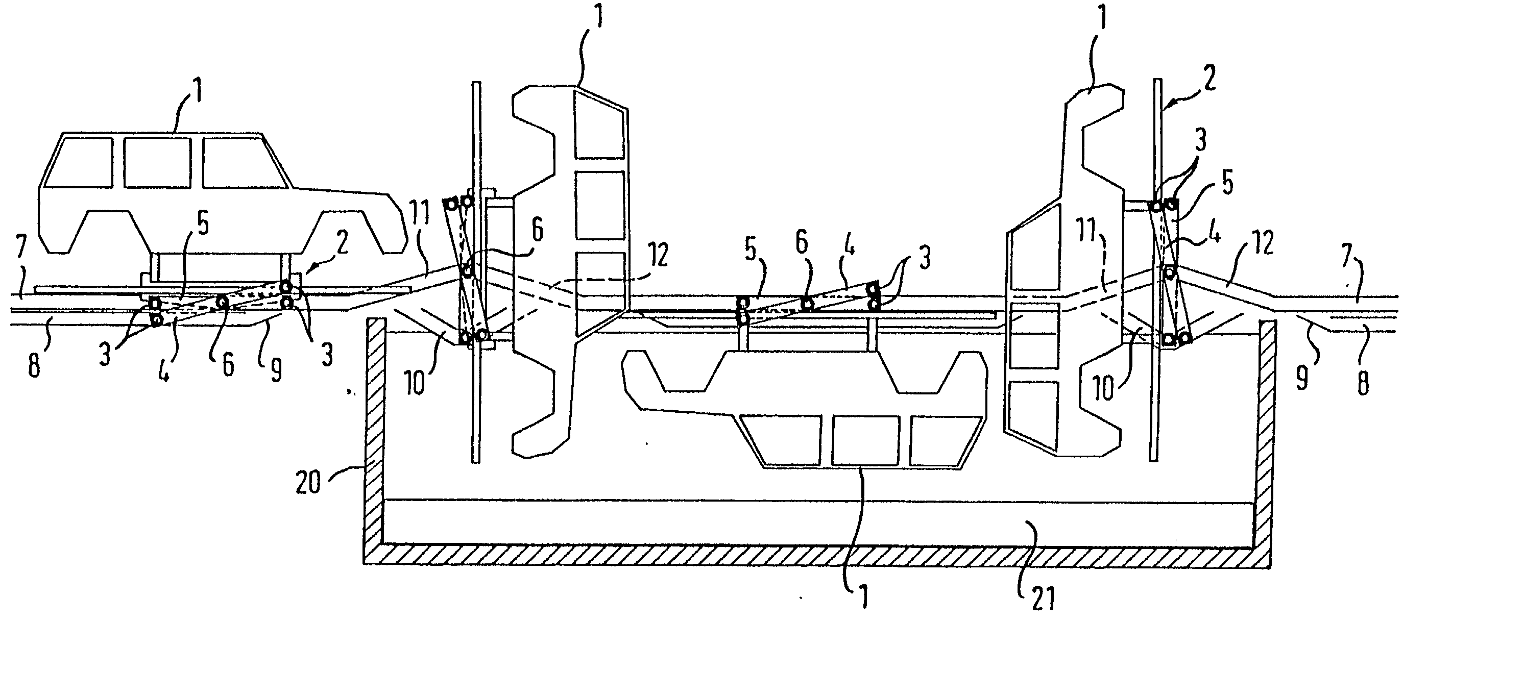
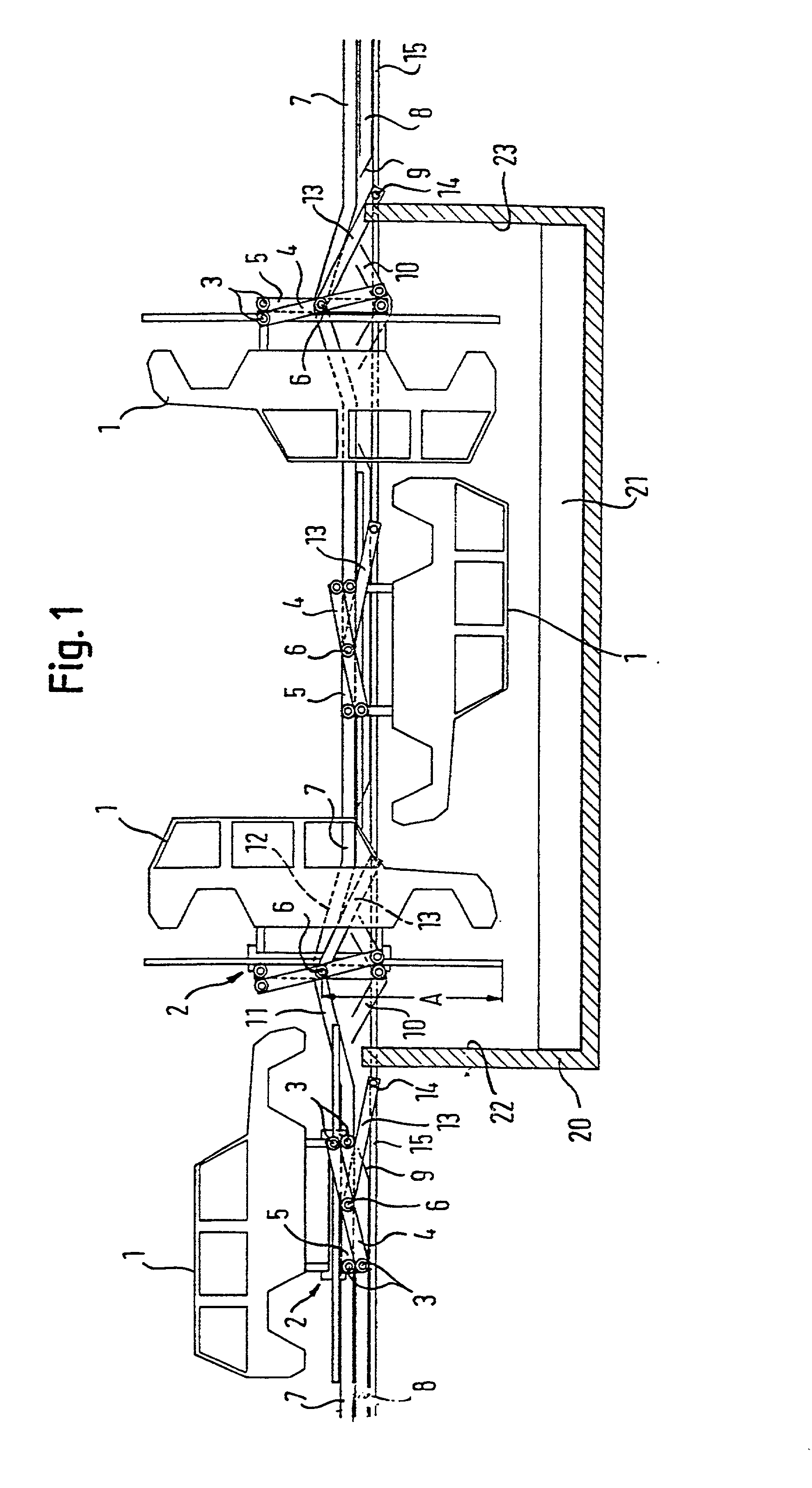
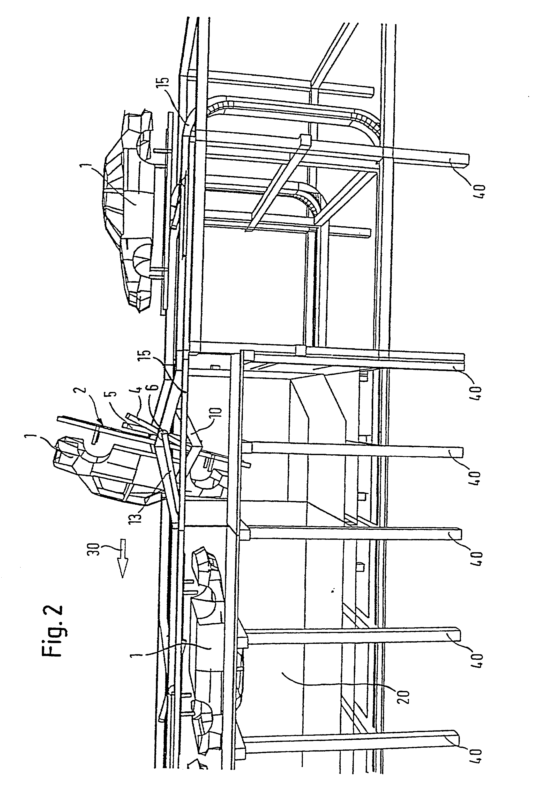
[0027] In the following, a first embodiment of the invention is explained in more detail with reference to FIGS. 1 and 2. As is shown in the views of FIGS. 1 and 2, a rotational axle guide 7 runs above a treatment bath 20 in lengthwise direction thereof. The rotational axle guide 7 consists of two rails running in parallel to each other which are spaced from each other and extend along the two longitudinal sides of the treatment bath. In these rails of the rotational axle guide 7, a rotational axle 6 of a holding frame 2 for a vehicle body 1 is supported for translational movement.

[0028] A holding frame 2 comprises a pick-up device which is not shown in detail, by means of which a vehicle body is detachably fastened to a holding frame 2. The pick-up device is known per se and may be designed in most different ways, for example as a hook, a clamping device, etc. At one long side a holding frame 2 is further equipped with two levers 4, 5 which are offset from each other at a certain a...


PUM


Abstract

The invention relates to a method for introducing and removing workpieces, especially vehicle bodies, into or from a treatment area (20) by rotational movements, whereby the treatment area serves for treating surfaces of the workpieces (1). A workpiece (1) is detachably fixed at a holding frame (2) which is moved together with at least one workpiece that is situated thereon at an essentially constant speed and by a continuous translation. The workpiece (1) is rotated around a rotational axle (6) at least at the beginning and end of the treatment area (20) and simultaneously with the translation movement. The rotational axle (6) is orientated vertically in relation to the moving direction of the holding frame (2) and is lifted and lowered during rotation.

Description

[0001] The invention relates to a method for introducing and removing workpieces, especially vehicle bodies, into or from a treatment area by means of an operation of introduction and removal, whereby said treatment area serves for treating the surfaces of the workpieces. According to the method, a workpiece is detachably fixed on a holding frame. The holding frame is moved together with the at least one workpiece that is situated thereon at an essentially constant speed by means of a continuous translation. The workpiece is rotated around a rotational axle at least at the beginning and the end of the treatment area and simultaneously with the translation movement, with the rotational axle being oriented vertically in relation to the moving direction of the holding frame. By the expression `at least at the beginning and the end`, those zones of the treatment areas are meant which are situated at the beginning and the end of a treatment basin, a treatment cabin, etc. It should be emp...

Claims


Application Information

Patent Timeline
IPC IPC(8): B05C3/10B62D65/00B05C13/00B05D1/18B05D3/00B65G49/04
CPCB65G49/0463B05C3/10
Inventor KREUZER, BERND
Owner ABB FLAEKT AB
Learn More