
Actuator and method for mounting an actuator

Inactive Publication Date: 2002-11-07
ROBERT BOSCH GMBH
View PDF4 Cites 14 Cited by
  • Summary
  • Abstract
  • Description
  • Claims
  • Application Information

AI Technical Summary

Benefits of technology

[0007] The actuator of the invention and the method of the invention for mounting an actuator, as defined by the bodies of claims 1 and 10, respectively, has the advantage over the prior art that in a simple way, the production process is simplified and the operating reliability is improved, and in addition mechanical stresses are reduced.[0008] By the provisions and method steps recited in the dependent claims 2-9 and 11, respectively, advantageous refinements of and improvements to the actuator defined by claim 1 and the method defined by claim 10 for mounting an actuator are possible.[0009] It is advantageous for the brush holders to be coupled loosely to the printed circuit board for installation in the actuator, because as a result the brush holder aligns itself with the commutator of the electric motor.[0010] It is also advantageous to couple the brush holder loosely to the printed circuit board by means of detent elements, because this simplifies the installation of the brush holder.[0011] Fastening the brush holder to the housing creates the advantage that the brush holder is decoupled from the printed circuit board, and mechanical vibration of the motor is not transmitted to the printed circuit board.[0012] It is also advantageous that electrical components are disposed movably in a receptacle on the brush holder, because as a result their electrical connection lines can be electrically connected to the printed circuit board without mechanical stresses, once the brush holder is mounted in the housing.[0013] For the mounting, it is advantageous that individual parts of the gear housing or of the electronics housing, which comprise at least one upper part and at one least lower part, are integral or are integral with the motor housing, because this reduces the number of parts to be mounted and reduces the effort and expense of production.[0014] The fixation of the printed circuit board in the housing is advantageously done by disposing elastic contact-pressure elements on the lower part of the housing, since as a result the printed circuit board is not secured rigidly to the housing.[0015] In the mounting of the actuator, it is advantageous for the detent hooks between the brush holder and the printed circuit board to be released.

Problems solved by technology

These devices have the disadvantage that the production process is very complicated and thus expensive.
Moreover, the solid connection of the brush holder and the printed circuit board has the disadvantage that a precise, simultaneous adaptation of tolerances of brush holders with carbon brushes to the commutator and printed circuit board with switch elements, such as Hall elements, which each have different system interfaces, proves to be quite difficult.

Method used


Image

  • Actuator and method for mounting an actuator
  • Actuator and method for mounting an actuator
  • Actuator and method for mounting an actuator

Examples


Embodiment Construction

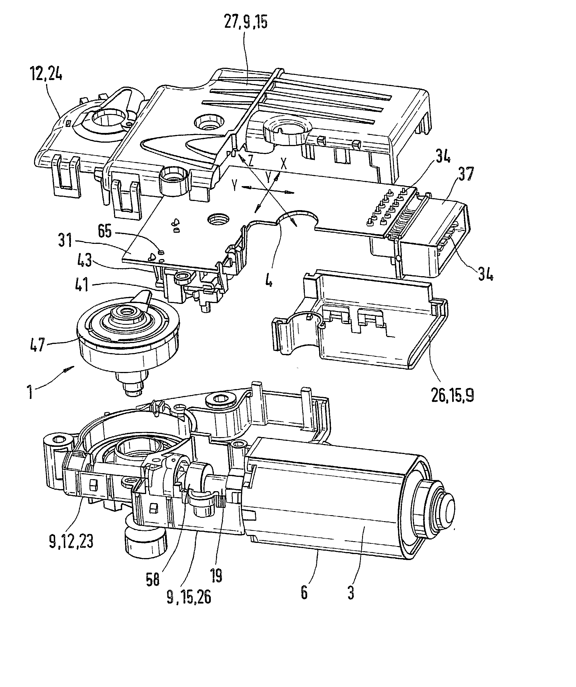
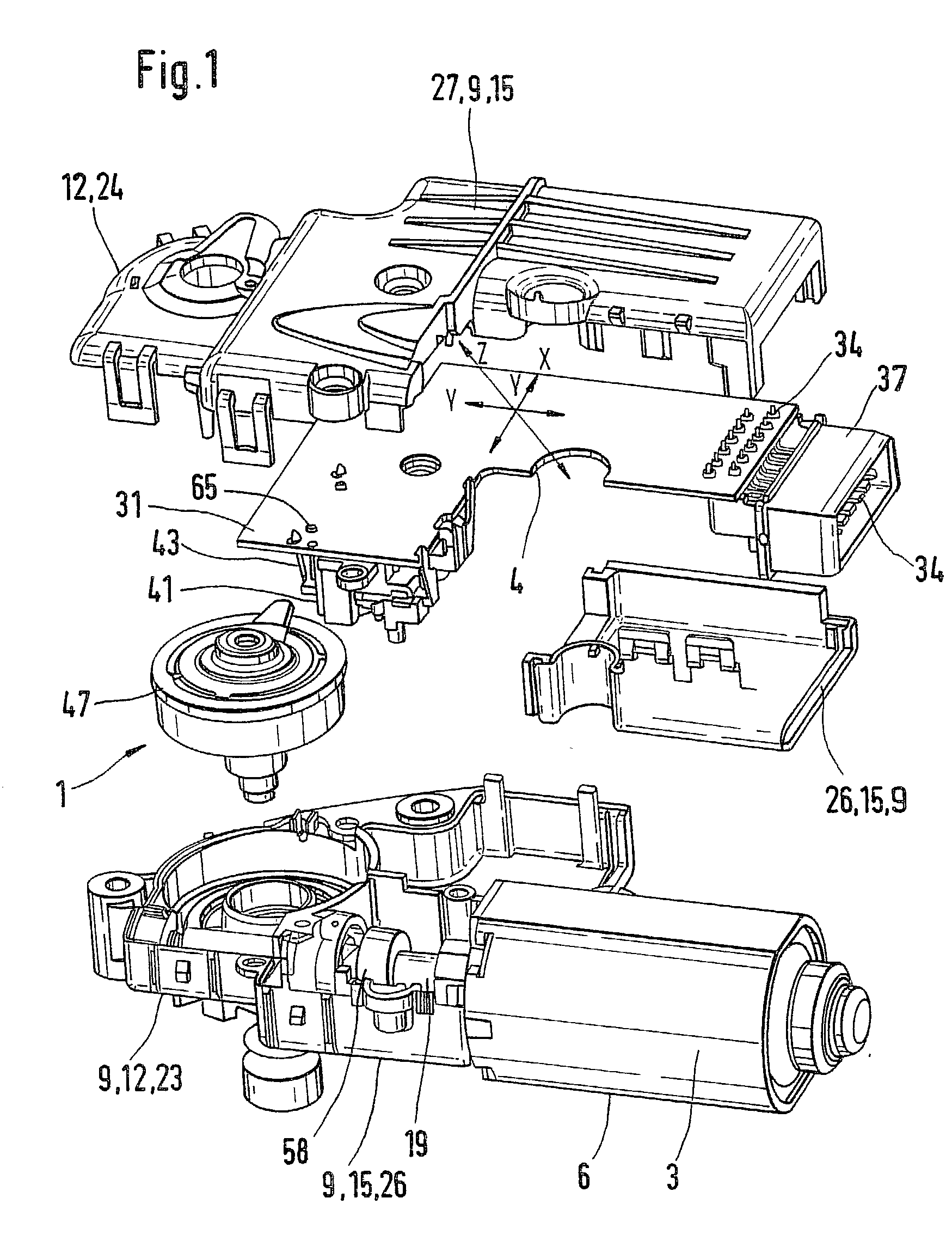
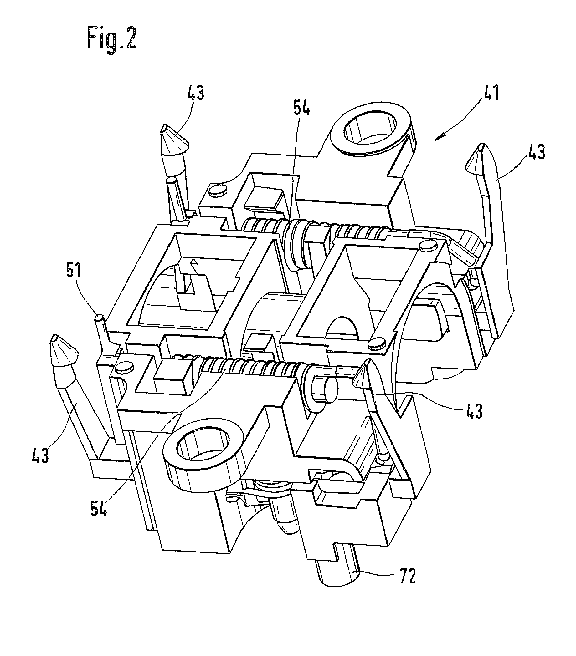
[0021] FIG. 1 shows an actuator 1. The actuator 1 has an electric motor 3, which is accommodated in a motor housing 6. Among other elements, the electric motor 3 comprises a stator and a rotor, whose shaft 19 protrudes out of the motor housing 6. The motor housing 6 is connected to a housing 9 into which the shaft 19 protrudes. The housing 9 includes a gear housing 12 and an electronics housing 15. The housing 9 has at least one upper part and at least one lower part. The gear housing 12 correspondingly has at least one upper part 23 and at least one lower part 24. By way of example, the electronics housing 15 likewise has at least one upper part 26 and at least one lower part 27. In this example, the lower part 24 of the gear housing 12 and the lower part 27 of the electronics housing are embodied integrally. The same can be provided accordingly for other individual parts of the housing 9. In addition, at least one part, such as an upper part 26 of the electronics housing and an up...


PUM


Abstract

An actuator in the prior art includes a plug contact, which is disposed on a printed circuit board, and also includes a brush holder, which is not disposed on the printed circuit board but is electrically connected to it. This has the disadvantage of requiring additional electrical connections. In an actuator (1) of the invention, the brush holder (41) is loosely coupled to the printed circuit board (31) and secured to a housing (9), so that electrical connections of the brush holder (41) and printed circuit board (31) are produced simply and without additional means.

Description

PRIOR ART[0001] The invention is based on an actuator and a method for mounting an actuator as generically defined by the preambles to claims 1 and 10, respectively.[0002] From European Patent Disclosure EP 0 865 148 A1, a commutator motor with a motor operation sensor is known, in which a plug is disposed on a printed circuit board. A brush holder is embodied separately from the printed circuit board.[0003] German Patent Disclosure DE 198 051 85 A1 shows a drive device in which a brush holder is embodied integrally with a plug receptacle. The receptacle is then mounted on a printed circuit board.[0004] From European Patent Disclosure EP 0 474 904 B1, a commutator-gear drive unit is known, in which a brush holder and a plug are disposed separately from one another on a printed circuit board.[0005] These devices have the disadvantage that the production process is very complicated and thus expensive. Moreover, the solid connection of the brush holder and the printed circuit board has...

Claims


Application Information

Patent Timeline
IPC IPC(8): H01R39/38H02K5/14H02K5/22H02K7/116H02K11/02H02K15/00H02K23/66
CPCH01R39/38H02K5/143H02K5/148H02K23/66H02K7/1166H02K11/026H02K15/00H02K5/225
Inventor MUELLER, MICHAELSTEUER, PETERHEITZ, ROBERTKOLMORGEN, STEFAN
Owner ROBERT BOSCH GMBH
Learn More