
Tiltable cargo box assembly with extension ramp

a cargo box and extension ramp technology, applied in the direction of bridges, transportation items, refuse gathering, etc., can solve the problems of sacrificing the exterior appearance of the vehicle, increasing the risk of injury to the person or persons operating the system and moving the load, and inadequate systems

Inactive Publication Date: 2002-11-07
ANGERMEIER GREGORY ROBERT
View PDF0 Cites 35 Cited by
  • Summary
  • Abstract
  • Description
  • Claims
  • Application Information

AI Technical Summary

Benefits of technology

[0006] It is another object of the invention to provide a cargo box assembly that can be installed on a conventional pick-up truck without altering the external appearance of the body of the truck.
[0007] It is another object of the invention to provide a cargo box assembly which is formed from components that are inexpensive and readily available the user in multiple forms.
[0008] It is another object of the invention to provide a cargo box assembly that utilizes the electrical system of the truck or other vehicle upon which it is installed as its primary source of power, thereby eliminating the need to move the ramp or cargo box manually, which in turn increases the safety of persons operating the cargo box assembly.
[0014] According to yet another preferred embodiment of the invention, the ramp assembly further includes first and second end rollers rotatably mounted on the first and second guide rails, respectively, for preventing the ramp from separating from the base plate when the ramp assembly is in the extended position.
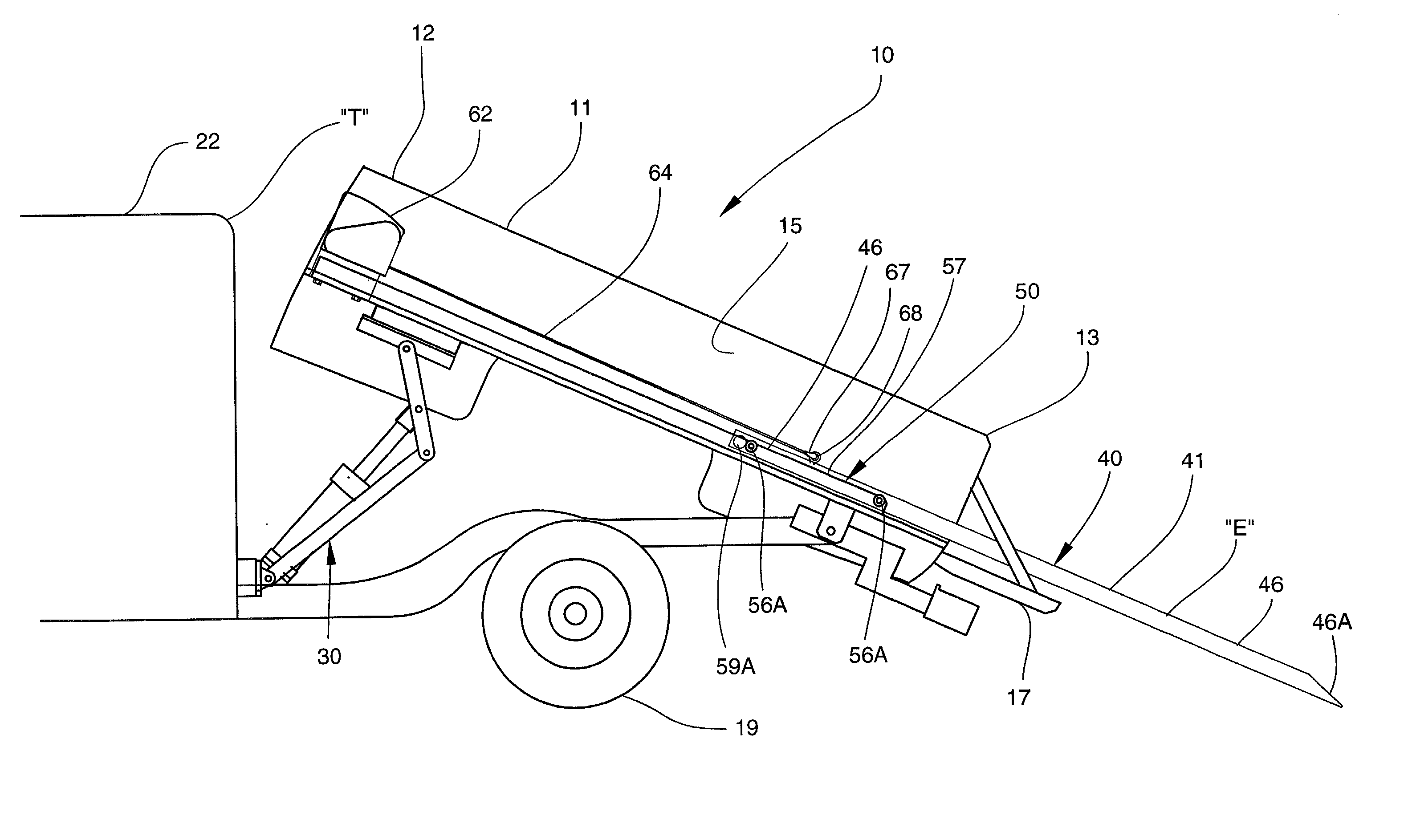
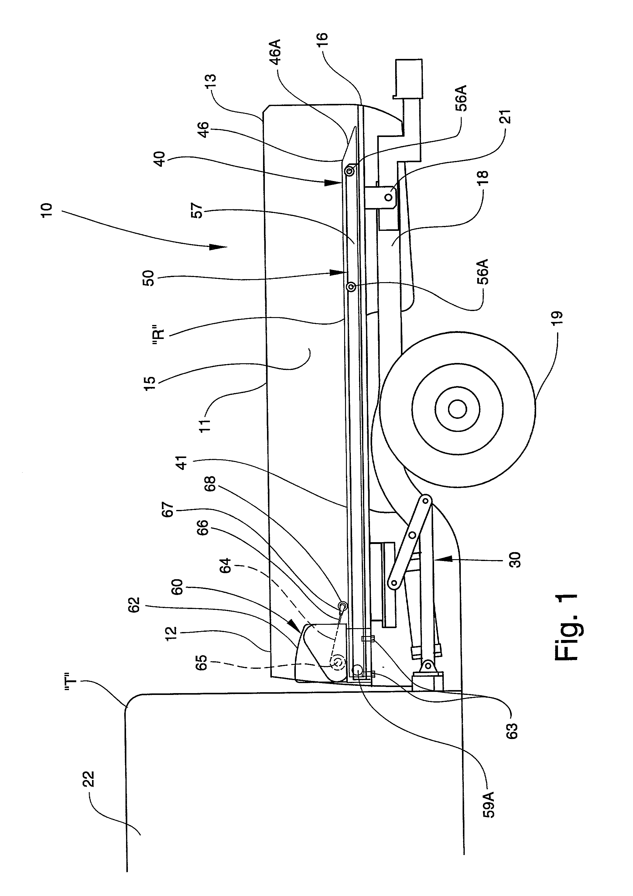
[0036] Referring now to FIGS. 4 and 5, the ramp assembly 40 and winch assembly 60 are shown removed from the cargo box 11 and truck "T" with the ramp 41 positioned in the extended and retracted positions, "E" and "R", respectively. As is shown in FIG. 4, two holes 46A and 46B are defined by respective forward ends 45 and 42A of the ramp 41 and base plate 42. Each hole 46A and 46B has a shape complementary to that of the outer case 62 for receiving the case 62 therein when the ramp 41 is in the retracted position "R". This permits the forward end 45 of the ramp 41 to completely cover the forward end 12 of the cargo box 11.
[0037] The ramp assembly 40 also includes four filler plates 47A, 47B, 47C, and 47D. Filler plates 47A and 47B are mounted to the floor 16 adjacent side edges 41A and 42B of the ramp 41 and base plate 42, respectively. Filler plates 47C and 47D are similarly mounted adjacent side edges 41B and 42B. As is shown in FIG. 6, the filler plates 47A-47D and ramp 41 create a raised floor 48. Raised floor 48 overlies the entire surface area of the floor 16 and thus prevents a load positioned on the ramp 41 from falling off the side edge 41A or 41B and becoming damaged.

Problems solved by technology

Although prior art cargo loading and unloading systems exist for use on standard pick-up trucks and other vehicles, such systems are inadequate due to limitations in structure and function.
For example, while some prior art systems include cargo boxes or platforms which may be tilted for permitting a load to be pushed or otherwise moved into the box or onto the platform, such systems lack extendable ramps, relying instead upon manual movement of the box or platform between elevated and lowered positions, which increases the risk of injury to the person or persons operating the system and moving the load.
Those prior art system providing extendable ramps do so at the expense of sacrificing the external appearance of the vehicle.
Such ramps cannot be installed on a conventional pick-up truck without permanently removing the tailgate and bumper, which irreversibly alters the structure and appearance of the back of the truck.

Method used


Image

  • Tiltable cargo box assembly with extension ramp
  • Tiltable cargo box assembly with extension ramp
  • Tiltable cargo box assembly with extension ramp

Examples


Embodiment Construction

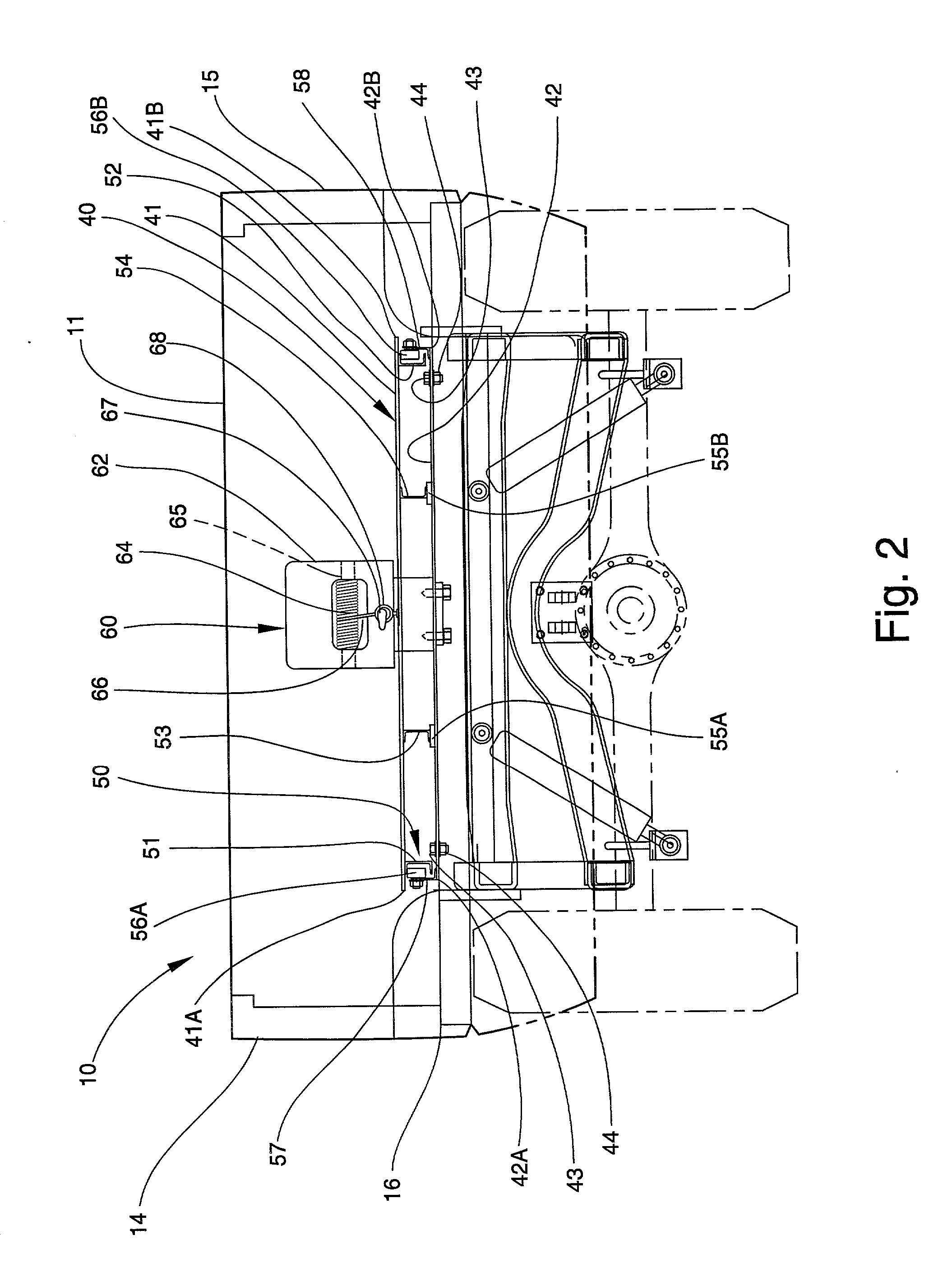
[0029] Referring now specifically to the drawings, a tiltable cargo box assembly according to the present invention is illustrated in FIG. 1 and shown generally at reference numeral 10. While the cargo box assembly 10 may be mounted and used on any vehicle having a cargo box or flat bed, the cargo box assembly 10 is preferably mounted on a standard pick-up truck "T". The cargo box assembly 10 includes a cargo box 11 which has forward and rear ends 12 and 13, respectively. As is shown in FIG. 2, the cargo box 11 also includes sidewalls 14 and 15 which are connected to opposing side edges of a floor 16 of the cargo box 11. As is shown in FIG. 3, the cargo box also includes a tailgate 17.

[0030] Referring again to FIG. 1, although a cargo box having any size or shape may be used, the cargo box 11 is preferably the standard, factory-installed cargo box included on the truck "T" at the time of purchase. However, unlike the factory-installed cargo box of a standard pick-up truck, which is ...


PUM


Abstract

A tiltable cargo box assembly for mounting on a vehicle, supporting a load, and transporting the load into and out / of the vehicle and includes a cargo box adapted for receiving the load therein. An attachment assembly is connected to a rear end of the box for pivotally mounting the box to the vehicle adjacent a rear axle thereof. A ramp assembly for carrying the load is slidably mounted to a floor of the box for reciprocating movement between extended and retracted positions relative to the floor. An actuator is mounted toward a forward end of the box intermediate the attachment assembly and a forward axle of the vehicle for being operatively connected to a power source of the vehicle and cooperates with the attachment assembly for moving the forward end between a lowered position and an elevated position wherein the floor is tilted at an angle relative to the lowered position for permitting the load to be transported into and out of the box.

Description

TECHNICAL FIELD AND BACKGROUND OF THE INVENTION[0001] This invention relates to a tiltable cargo box assembly for use on a vehicle, such as a pick-up truck. The cargo box assembly includes an extendable ramp, and is used for loading and unloading heavy objects onto and off of the vehicle. Such objects include, but are not limited to, lawn mowers, garden tractors, small motorcycles, other similarly sized all-terrain vehicles and any other large objects which could not otherwise be easily lifted into or out of the vehicle. The unique structure of the cargo box assembly of the present invention permits such objects to be loaded onto and unloaded from the truck safely and efficiently.[0002] Although prior art cargo loading and unloading systems exist for use on standard pick-up trucks and other vehicles, such systems are inadequate due to limitations in structure and function. For example, while some prior art systems include cargo boxes or platforms which may be tilted for permitting a...

Claims


Application Information

Patent Timeline
IPC IPC(8): B60P1/16B60P1/43B60P3/12
CPCB60P1/16B60P3/122B60P1/433
Inventor ANGERMEIER, GREGORY ROBERT
Owner ANGERMEIER GREGORY ROBERT
Learn More