Low latency FIFO circuits for mixed asynchronous and synchronous systems

a technology of mixed asynchronous and synchronous systems, applied in the field of low latency fifo, can solve the problems of long delays in communication between systems, few adequate solutions, and complex interface between these domains

Inactive Publication Date: 2002-11-14
THE TRUSTEES OF COLUMBIA UNIV IN THE CITY OF NEW YORK
View PDF0 Cites 34 Cited by
  • Summary
  • Abstract
  • Description
  • Claims
  • Application Information

AI Technical Summary

Problems solved by technology

A challenging problem is to robustly interface these domains.
There have been few adequate solutions, especially ones providing reliable low-latency communication.
There are two fundamental challenges in designing systems-on-a-chip.
A first challenge concerns systems operating under different timing assumptions.
A second challenge concerns designs having long delays in communication between systems.
Some designs are limited to handling single-clock systems.
However, the latency of this design is proportional with the number of FIFO stages, whose implementation include expensive synchronizers.
This approach changes the local systems' clocks, and may introduce latency penalties in restarting them.
However, the FIFO circuit described in '113 has a significantly greater area overhead in implementing the synchronization.

Method used


Image

  • Low latency FIFO circuits for mixed asynchronous and synchronous systems
  • Low latency FIFO circuits for mixed asynchronous and synchronous systems
  • Low latency FIFO circuits for mixed asynchronous and synchronous systems

Examples


first embodiment

[0112] Cell 170a in accordance with the first embodiment is also shown in FIG. 16. The behavior of cell 170a may be illustrated by tracing a put operation and then a get operation through the cell 170a. Initially, the cell 170a starts in an empty state (i.e., e_i=1 and f_i=0) and without any tokens. The cell 170a waits to receive the put token on put token input 190 (ptokn_in=1) from the right cell on the positive edge of sender clock signal 12 (CLK_put), and waits for the sender to place a valid data item on the put data bus 16 (data_put). A valid data item is indicated to all cells by the put enable signal 180 (en_put=1), which is the output of the put controller 176 (See FIG. 6).

[0113] When there is valid data and the cell has obtained the put token (i.e., AND 181), the cell 170a performs three actions: (1) it enables the register 191 (REG) to latch the data item and also the put request signal 14 (req_put); (2) it indicates that the cell 170a has a valid data item (asynchronousl...

second embodiment

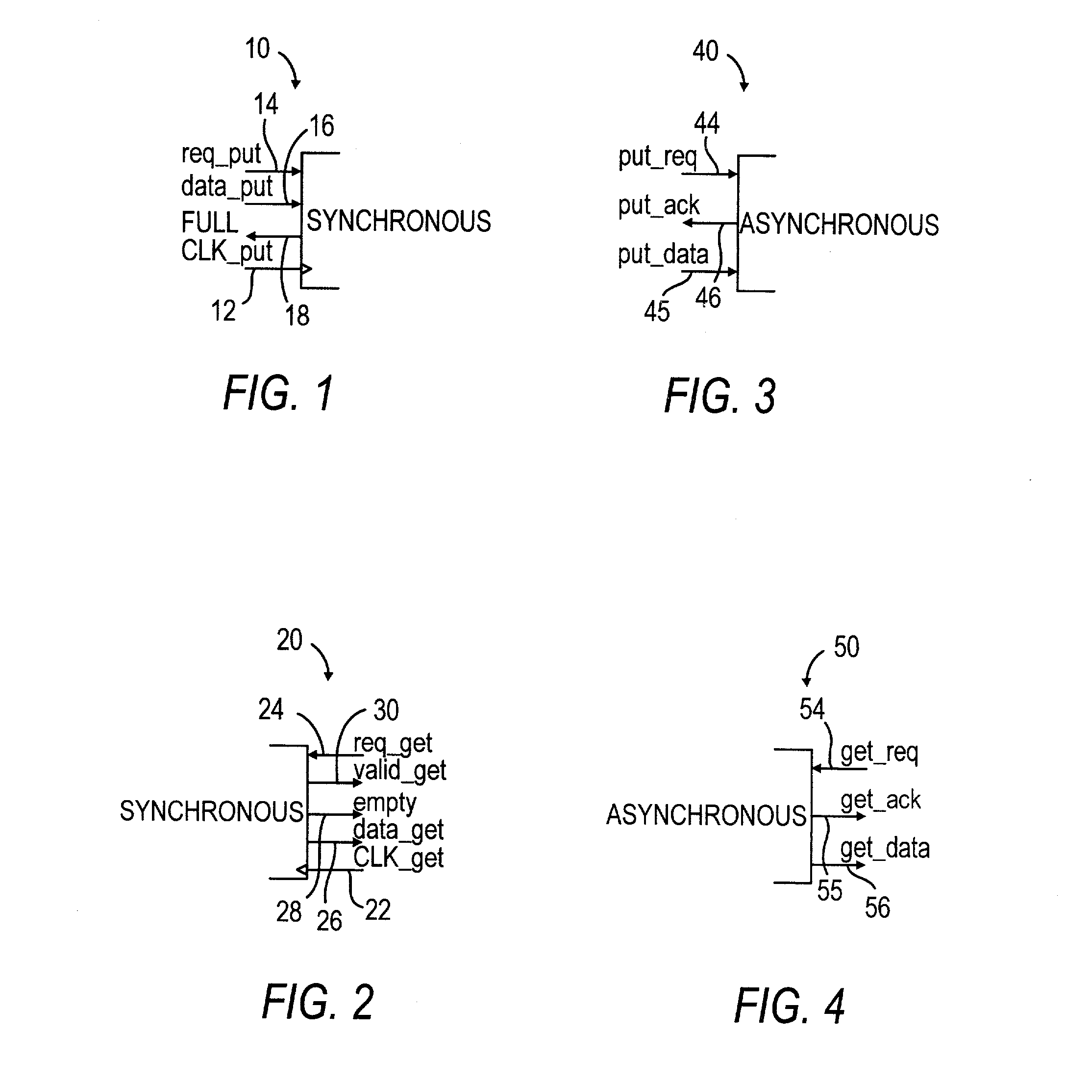
[0132] The interfaces of the FIFO circuit i.e., asynch-synch FIFO circuit 200, were described above with respect to FIG. 7. They are obtained by using the asynchronous put interface 40 (FIG. 3) and the synchronous get interface 20 (FIG. 2). The FIFO circuit protocol on these interfaces was described with respect to FIGS. 12-13, and the architecture of the FIFO circuit 200 was shown in FIGS. 7-8. With specific reference to FIG. 8, FIFO circuit 200 uses a number of components which have been described above, i.e., interface components such as the get controller 278, empty detector 74 and synchronous cell components. The remaining components in cells 270a-d, i.e., the asynchronous put component, and the data validity controller are described herein with respect to FIGS. 22-23.

[0133] The synchronous part of cell 270a shown in FIG. 23 is identical to the corresponding components of cell 170a (FIG. 16) in FIFO circuit 100 (FIG. 6). The asynchronous part of cell 270a is decomposed into se...

example

[0198] EXAMPLE

[0199] In order to evaluate the performance of the various FIFO circuit designs, Each of the exemplary FIFO circuit 100, 200, 300, 500, 600, and 700 were simulated. Each FIFO circuit was simulated using both commercial and academic tools. The designs were built using both library and custom circuits, and were simulated using Cadence HSPICE. The Burst-Mode controllers were synthesized using Minimalist (Minimalist is described in greater detail in R. Fuhrer et al., "MINIMALIST: An Environment for Synthesis, Verification and Testability of Burst-Mode Asynchronous Machines," CUCS-020-99, 1999, which is incorporated by reference in its entirety herein.) and the Petri-Net controllers were synthesized using Petrify (Petrify is described in greater detail in J. Cortadella et al., "Petrify: A Tool for Manipulating Concurrent Specifications and Synthesis of Asynchronous Controllers," IEICE Transactions on Information and Systems, Vol. E80-D, Number 3, pp. 315-325, March 1997, wh...


PUM


Abstract

A FIFO design interfaces a sender subsystem and a receiver subsystem operating on different time domains. The sender subsystem and the receiver subsystem may be synchronous or asynchronous. The FIFO circuit includes a put interface configured to operate in accordance with the sender time domain and get interface configured to operate in accordance with the receiver time domain. The FIFO circuit includes an array of cells having a register and state controller indicative of the state of the cell. Each cell also has a put component part configured to operate according to the sender time domain including a put token passing circuit and put controller circuit. Each cell has get component part configured to operate according to the receiver time domain including a get token passing circuit and a get controller circuit. A mixed-clock relay station design interfaces a sender subsystem and a receiver subsystem working at different time domains, and where the latency between sender and receiver is large.

Description

[0001] This application claims priority to U.S. Provisional Patent Application entitled "Low-Latency FIFO For Mixed-Clock Systems," Serial No. 60 / 210,642, which was filed on Jun. 9, 2000, and U.S. Provisional Patent Application entitled "Low-Latency Asynchronous FIFO's Using Token Rings," Serial No. 60 / 210,644, filed Jun. 9, 2000, both of which are incorporated by reference in their entirety herein.[0002] 1. FIELD OF THE INVENTION[0003] This invention relates to FIFO circuits, and more particularly to low latency FIFO designs that interface subsystems working at different speeds and that may be synchronous or asynchronous, and between subsystems with very long interconnection delays.[0004] 2. BACKGROUND OF RELATED ART[0005] A trend in VLSI is increasingly towards a "system-on-a-chip" involving many clock domains. A challenging problem is to robustly interface these domains. There have been few adequate solutions, especially ones providing reliable low-latency communication.[0006] Th...

Claims


Application Information

Patent Timeline
Patent Type & Authority Applications(United States)
IPC IPC(8): G06F5/10G06F5/14
CPCG06F5/14
Inventor CHELCEA, TIBERIUNOWICK, STEVEN M.
Owner THE TRUSTEES OF COLUMBIA UNIV IN THE CITY OF NEW YORK
Why Eureka
Try Eureka