Optical fiber laser structure and system based on ase pumping of cladding element

a technology of optical fiber laser and cladding element, applied in the direction of laser details, excitation process/apparatus, active medium material, etc., can solve the problems of limited application of cladding pumping structure disclosed in the 501 patent, deficiency of conventional cladding pumping optical fiber laser structure,

Inactive Publication Date: 2002-11-21
KIGRE
View PDF0 Cites 3 Cited by
  • Summary
  • Abstract
  • Description
  • Claims
  • Application Information

AI Technical Summary

Benefits of technology

[0008] An optical fiber laser structure and system are disclosed. The optical fiber laser structure includes a core element and a cladding element. The core element has a first and second end. The core element includes a first active gain component. The cladding element at least partially surrounds the core element. The cladding element has a length defined between the first and second ends of the core element.[0009] The cladding element includes a second active gain component that is different from the first active gain component. The second active gain component is suitable for achieving amplified spontaneous emission (ASE) in the cladding element. More specifically, the second active gain component is suitable for achieving ASE in the cladding element along the length between the first and second ends of the core element. As a result, energy is efficiently transferred to the first active gain component in the core element to provide laser activity at a laser wavelength of from 1500 to 1600 nanometers. The optical fiber laser system of the subject invention additionally includes a pumping source. The pumping source is coupled to the cladding element to provide the energy to the cladding element such that the second active gain component achieves the ASE.[0010] Accordingly, the subject invention provides an optical fiber laser structure and system including a core element and an ASE-pumped cladding element that provides laser activity at a laser wavelength of from 1500 to 1600 nanometers.[0011] Other advantages of the present invention will be readily appreciated as the same becomes better understood by reference to the following detailed description when considered in connection with the accompanying drawings wherein:[0012] FIG. 1 is a cross-sectional view of an optical fiber laser system including an optical fiber laser structure in combination with a pumping source and an imaging device;[0013] FIG. 2 is a cross-sectional view of the optical fiber laser structure including more than one core element; and[0014] FIG. 3 is a partially cross-sectional side view of the optical fiber laser system.

Problems solved by technology

As a result, optical fiber laser structures can be developed with power densities that are only limited by material considerations and the ability to introduce energy, through the pumping sources, into the optical fiber laser structure.
Conventional cladding-pumped optical fiber laser structures, including the cladding-pumped structure disclosed in the above-referenced patent, are deficient for various reasons.
Therefore, the cladding-pumped structure disclosed in the '501 patent has limited application as it is not suitable for providing laser activity at a laser wavelength of from 1500 to 1600 nm.
The cladding-pumped optical fiber laser structures of the prior art are also deficient because these structures rely on lasing to transfer energy to the core element.
Simply stated, reliance on lasing to transfer energy to the core element is not as efficient as utilizing amplified spontaneous emission to transfer the energy to the core element.

Method used


Image

  • Optical fiber laser structure and system based on ase pumping of cladding element
  • Optical fiber laser structure and system based on ase pumping of cladding element

Examples


Embodiment Construction

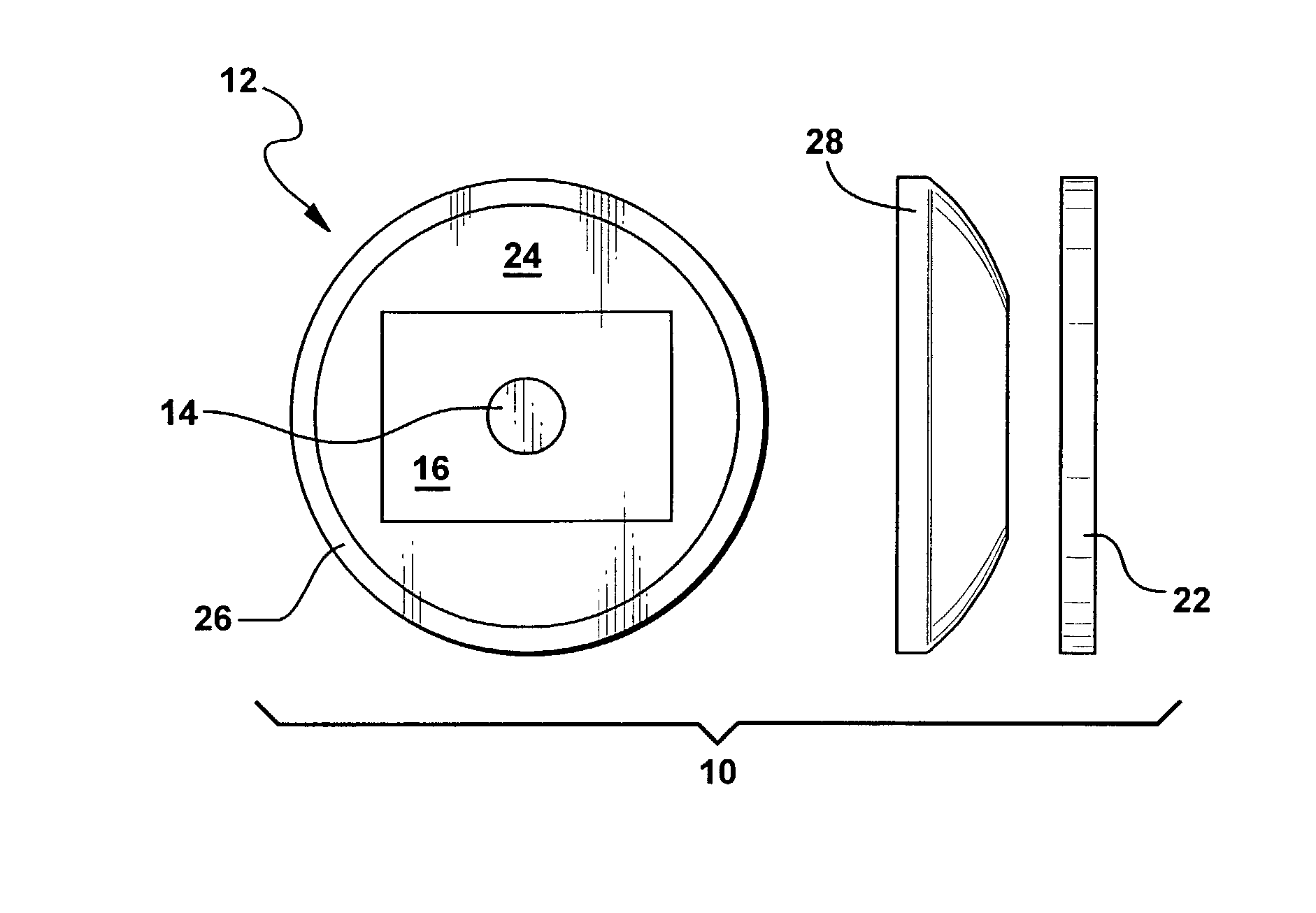
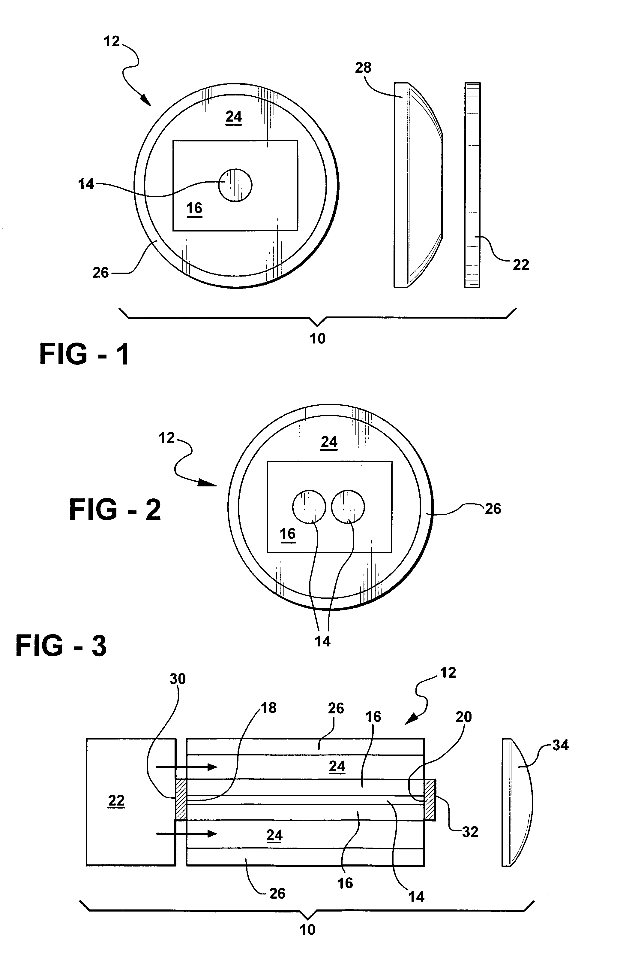
[0015] Referring to the Figures, wherein like numerals indicate like or corresponding parts throughout the several views, an optical fiber laser system is generally disclosed at 10. The optical fiber laser system includes an optical fiber laser structure that is generally disclosed at 12 throughout the Figures. It is to be understood that FIGS. 1 through 3, disclosing the optical fiber laser system 10 and the optical fiber laser structure 12 of the subject invention, are not necessarily to scale.

[0016] The optical fiber laser system 10, hereinafter referred to as "the system," and the optical fiber laser structure 12, hereinafter referred to as "the structure," according to the subject invention provide laser activity, or laser radiation, at a laser wavelength of from 1500 to 1600, preferably from 1530 to 1545, and most preferably at 1535, nanometers (nm). This laser wavelength is an eye-safe wavelength that can be utilized in an eye-safe laser. It is generally understood that eye-s...


PUM


Abstract

An optical fiber laser structure and system are disclosed. The fiber laser structure includes a core, an inner cladding, and an outer cladding. The core has a first and second end and includes a combination of ytterbium and erbium as a first active gain component. The inner cladding, having a length defined between the first and second ends, surrounds the core. The inner cladding includes neodymium as a second active gain component that is different from the first active gain component. The system includes a pumping source coupled to the inner cladding to provide energy to the neodymium in the inner cladding. Upon being pumped, the neodymium achieves amplified spontaneous emission in the inner cladding along the length between the first and second ends. As a result, energy is efficiently transferred from the neodymium to the combination of the ytterbium and erbium in the core thereby providing laser activity at an eye-safe laser wavelength of 1535 nanometers.

Description

[0001] 1) Field of the Invention[0002] The subject invention generally relates to an optical fiber laser structure and system. More specifically, the subject invention relates to an optical fiber laser structure and system including a core element and an ASE-pumped cladding element providing laser activity at a laser wavelength of from 1500 to 1600 nanometers.[0003] 2) Description of Related Art[0004] Optical fiber laser structures and systems are known in the art. Cladding-pumped optical fiber laser structures and systems are also known in the art. Cladding-pumped optical fiber laser structures and systems are utilized throughout the medical and telecommunication industries. More specifically, cladding-pumped optical fiber laser structures and systems have advanced the state-of-the-art in these industries by permitting pumping of single-mode core elements with multi-mode high power pumping sources. As a result, optical fiber laser structures can be developed with power densities th...

Claims


Application Information

Patent Timeline
Patent Type & Authority Applications(United States)
IPC IPC(8): H01S3/067H01S3/094H01S3/16
CPCH01S3/06708H01S3/06716H01S3/06729H01S3/06737H01S3/094007H01S2302/00H01S3/1608H01S3/1611H01S3/1618H01S2301/02H01S3/094023
Inventor MYERS, JOHN D.MYERS, MICHAEL J.
Owner KIGRE
Why Eureka
Try Eureka