Surface-mount positive coefficient thermistor and method for making the same

a positive coefficient and thermistor technology, applied in the field of surface-mount positive coefficient thermistors, can solve the problems of substantial deterioration of the wettability of the solder when a board is mounted

Inactive Publication Date: 2002-11-28
MURATA MFG CO LTD
View PDF0 Cites 14 Cited by
  • Summary
  • Abstract
  • Description
  • Claims
  • Application Information

AI Technical Summary

Problems solved by technology

If heat is applied for a sufficiently long time to completely melt the solder 5, the end 4a of the metal terminal 4 is discolor

Method used


Image

  • Surface-mount positive coefficient thermistor and method for making the same
  • Surface-mount positive coefficient thermistor and method for making the same
  • Surface-mount positive coefficient thermistor and method for making the same

Examples


Embodiment Construction

30 Melted Not observed 19 N COMPARATIVE 30 Not melted Not observed --EXAMPLE COMPARATIVE 120 Melted Observed 18 N EXAMPLE

[0036] Table 1 demonstrates that the solder 5 of the known surface-mount positive coefficient thermistor 1 is not completely melted during a heating time of about 30 seconds, resulting in unsuccessful connection between the metal terminal 4 and the electrode 3. Furthermore, the plated tin at the end 4b of the metal terminal 4 is discolored by oxidation during a prolonged heating time of about 120 seconds though the connection is completed due to melting of the solder 5.

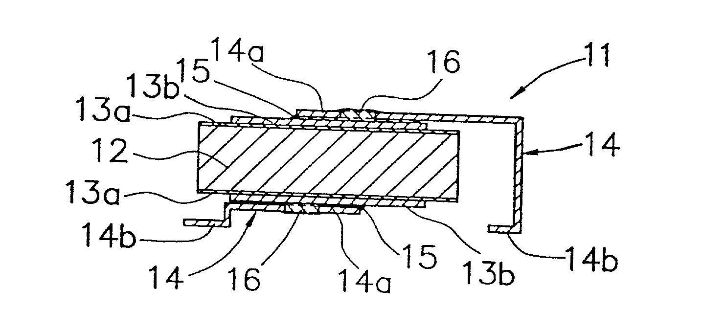
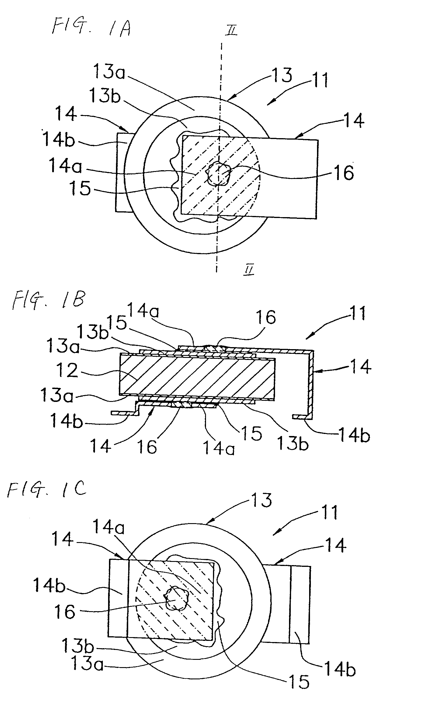
[0037] In contrast, in the surface-mount positive coefficient thermistor 11 according to preferred embodiments of the present invention, the solder is melted during a heating time of about 30 seconds to completely and reliably connect the metal terminal 14 to the electrode 13 by soldering. The end 14b of the metal terminal 14 is not discolored.

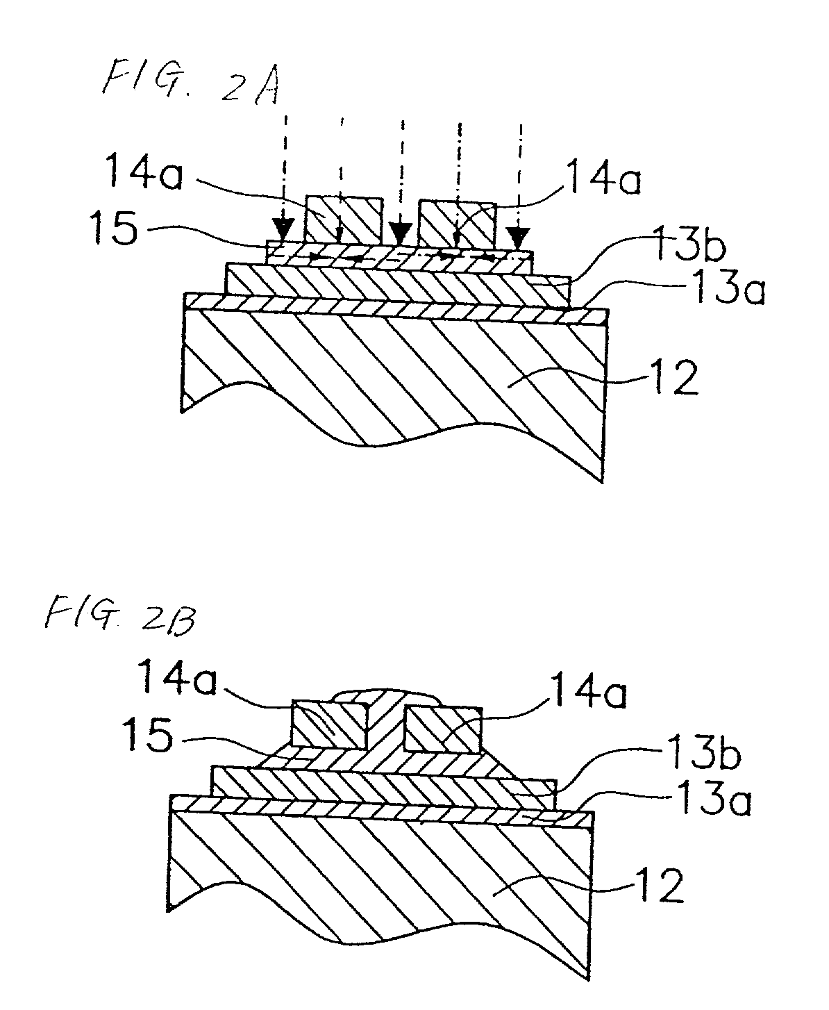
[0038] This is because the hole 16 at the end 14a of the...


PUM

PropertyMeasurementUnit
Areaaaaaaaaaaa
Heataaaaaaaaaa

Abstract

A surface-mount positive coefficient thermistor includes a plate-like positive coefficient thermistor element, a pair of electrodes on the respective two main surfaces of the positive coefficient thermistor element, a pair of metal terminals each having a cutout at one end region connected to the corresponding electrode, the metal terminals including a metal having a low thermal conductivity, and solders each connecting the end region of the corresponding metal terminal to the outermost layer of the corresponding electrode. The metal terminal is readily and uniformly soldered to the electrode in a short period of time.

Description

[0001] 1. Field of the Invention[0002] The present invention relates to surface-mount positive coefficient thermistors for use in, for example, protecting exchanges and telephones from overcurrents.[0003] 2. Description of the Related Art[0004] FIGS. 4A and 4B show a surface-mount positive coefficient thermistor 1 which includes a surface-mount type disc positive coefficient thermistor element 2. A pair of electrodes 3 is provided on two main surfaces of the disc positive coefficient thermistor element 2. Each electrode 3 includes a nickel-plated underlayer 3a and a silver-baked outermost layer 3b. Furthermore, one end 4a of a pair of metal plate terminals 4 are connected to each outermost layer 3b via solder 5. The metal terminals 4 are made of nickel silver or stainless steel and are plated with tin. The other end of each metal terminal 4 is connected to an electric circuit (not shown) on a board with solder.[0005] In the surface-mount positive coefficient thermistor 1, the metal ...

Claims


Application Information

Patent Timeline
IPC IPC(8): C04B35/46H01C1/14H01C1/144H01C7/02H05K3/34
CPCH01C1/1406H05K3/3426H01C1/144Y02P70/50
Inventor KATSUKI, TAKAYONISHIBORI, MASANORI
Owner MURATA MFG CO LTD
Why Eureka
Try Eureka