
Propulsion device, in particular for a rocket

a technology for rockets and propellants, which is applied in the direction of machines/engines, nuclear power plants, nuclear engineering, etc., can solve the problems of physical limits of this parameter, relatively difficult to obtain sufficient payload, and slow progress

Inactive Publication Date: 2002-12-12
EUROPEAN SPACE AGENCY
View PDF0 Cites 16 Cited by
  • Summary
  • Abstract
  • Description
  • Claims
  • Application Information

AI Technical Summary

Benefits of technology

0034] An object of the present invention is to overcome, at least in part, the limits stated above c

Problems solved by technology

Improvements in rocket propulsion are tending to increase this specific impulse, but there are physical limits on this parameter and progress has been very slow over recent decades.
With prior art rocket propulsion, it is relatively difficult to obtain sufficient payload when using a spacecraft of the SSTO type.
The present limits on specific impulse Isp performance of chemical propulsion are due to physical limitations, the most important of which is the choice of propellant.
Small improvements can be obtained by increasing the pressure in the combustion chamber, but at the cost of increased technological difficulties.
it is difficult to make the internal temperature of the nuclear core uniform; as a result there is a risk of the engine being degraded because temperature margins are small compared with the technological limits of the materials.
Furthermore, the use of a nuclear thermal engine has been envisaged until now solely for interplanetary missions, given that for an orbital mission, non-recoverable launcher debris will fall out on Earth.
At the time when that type of propulsion was being studied, recoverable launchers were a long way from becoming available.
There are technical limits on the heating of gas, thus giving rise to limits concerning specific impulse Isp.
It will be observed that until now, the use of diversified heat sources or the introduction of heat at different locations has not been tried.
Consequently, the mean weight / thrust ratio for such devices in the present prior art is most unfavorable (about 1000).

Method used


Image

  • Propulsion device, in particular for a rocket
  • Propulsion device, in particular for a rocket
  • Propulsion device, in particular for a rocket

Examples


Embodiment Construction

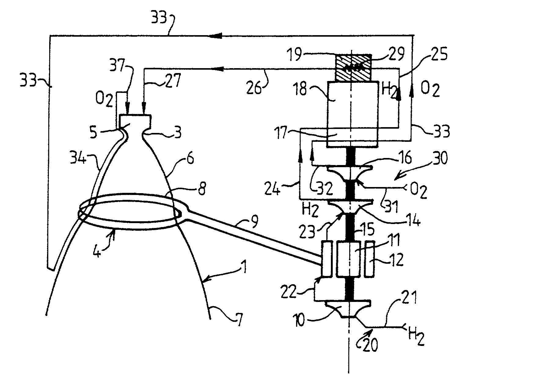
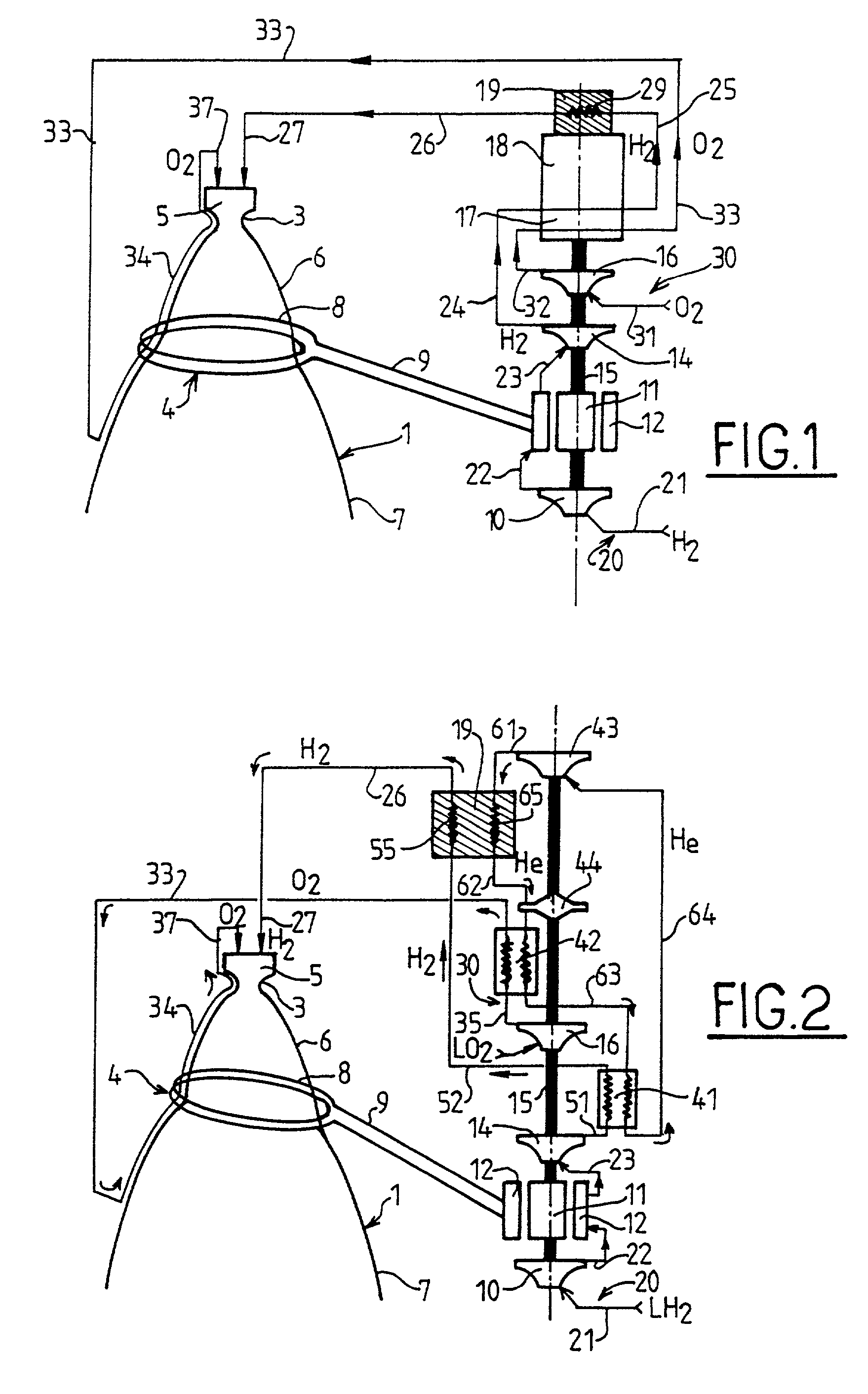
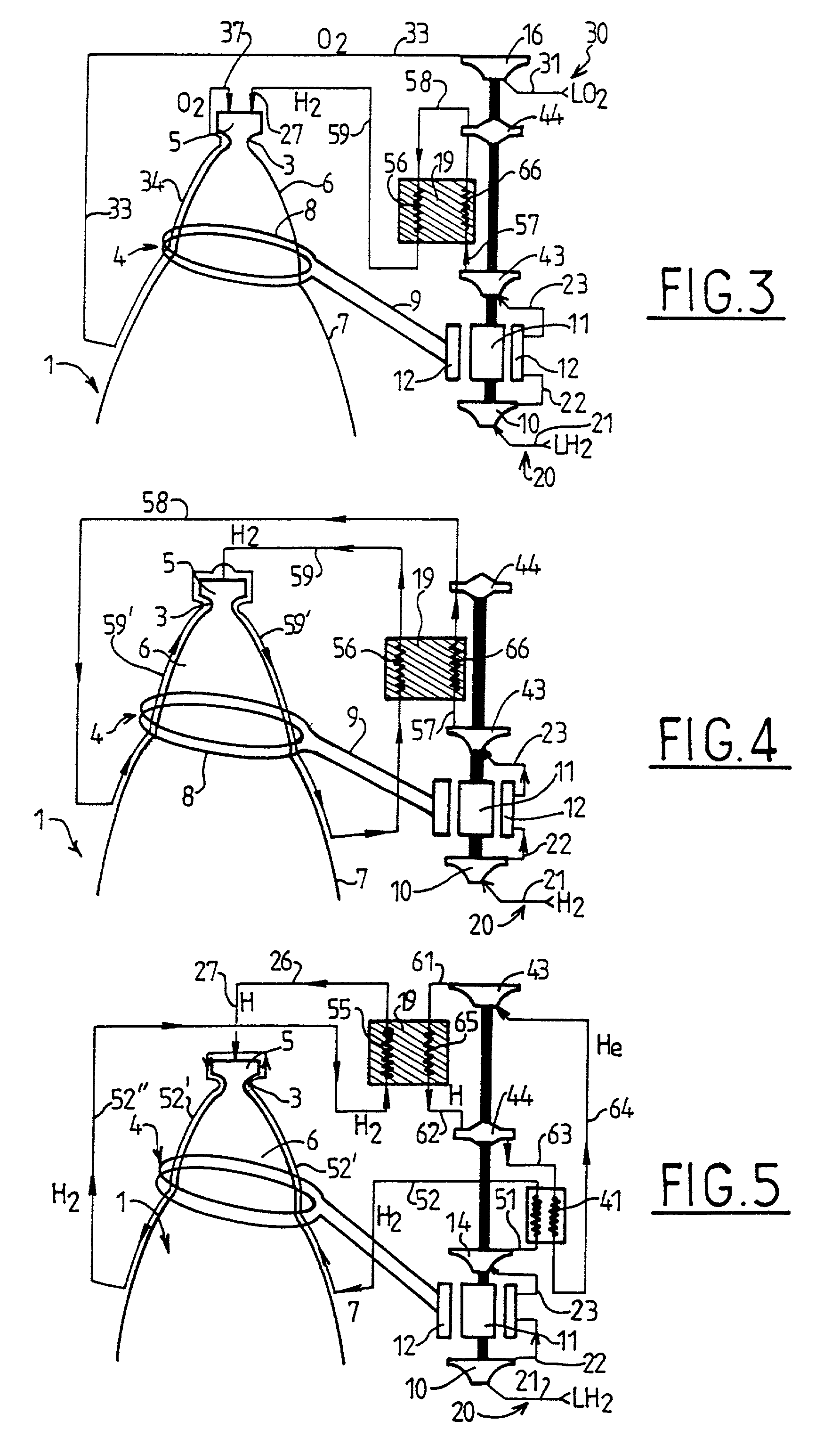
[0069] The propulsion device of induction nuclear chemical type shown in FIG. 1 has a hydrogen circuit 20 which comprises a duct 21 for feeding hydrogen to a pump 10 which feeds a duct 22 and whose outlet is connected to the inlet of a cooling circuit 12 for cooling an electricity generator 11. The cooling circuit 12 has an outlet connected to a duct 23 which feeds a pump 14 which directs hydrogen via a duct 24 causing it to pass through a heat exchanger 17 where it serves as a heat sink for a heat engine 18, after which, in order to be heated, a duct 25 causes it to pass through a heat exchanger 29 of a nuclear core 19 which serves as a heat source for the heat engine 18. Downstream from the nuclear core 19, the duct 26 directs the gaseous hydrogen to a duct 27 for feeding an injection chamber 5 disposed upstream from a nozzle 1 which has a throat 3 and which flares progressively at 6 and at 7, the flared regions 6 and 7 being separated by a region 4 in which an induction loop 8 is...


PUM


Abstract

The invention relates to a propulsion device comprising a gas ejection nozzle and an injection chamber for injecting at least one propellant fluid. According to the invention, the device has an induction loop which surrounds a zone of the nozzle and also an electricity generator to feed said induction loop, in particular under drive from a heat engine whose heat source is a nuclear core and whose heat sink is a cryogenic liquid which is subsequently used for propulsion.

Description

[0001] Rocket propulsion is the only means that can be used beyond the atmosphere. The size of a space vessel depends essentially on its specific impulse Isp which is given by the conventional formula:.DELTA.V=g.sub.0.Isp ln(m.sub.1 / m.sub.0) (I)[0002] in which .DELTA.V is the speed increment, g.sub.0 is the attraction due to gravity, m.sub.1 is the launch mass, m.sub.0 is the orbital mass, and ln is the natural logarithm.[0003] Improvements in rocket propulsion are tending to increase this specific impulse, but there are physical limits on this parameter and progress has been very slow over recent decades.[0004] The above formula can be applied in particular to a single stage to orbit (SSTO) spacecraft that has been put into orbit. The speed increment .DELTA.V necessary to reach low earth orbit (LEO) is about 9,000 meters per second, including losses. By convention, the residual mass of fuel can be considered as being a portion of the payload m.sub.p. The mass in orbit m.sub.0 is th...

Claims


Application Information

Patent Timeline
IPC IPC(8): F02K99/00F03H99/00
CPCF03H99/00
Inventor DUJARRIC, CHRISTIAN FRANCOIS MICHEL
Owner EUROPEAN SPACE AGENCY
Learn More