Apparatus for driving brushless motor
- Summary
- Abstract
- Description
- Claims
- Application Information
AI Technical Summary
Benefits of technology
Problems solved by technology
Method used
Image
Examples
Embodiment Construction
[0035] Hereinafter, a preferred embodiment of the present invention will be explained with reference to figures, as follows.
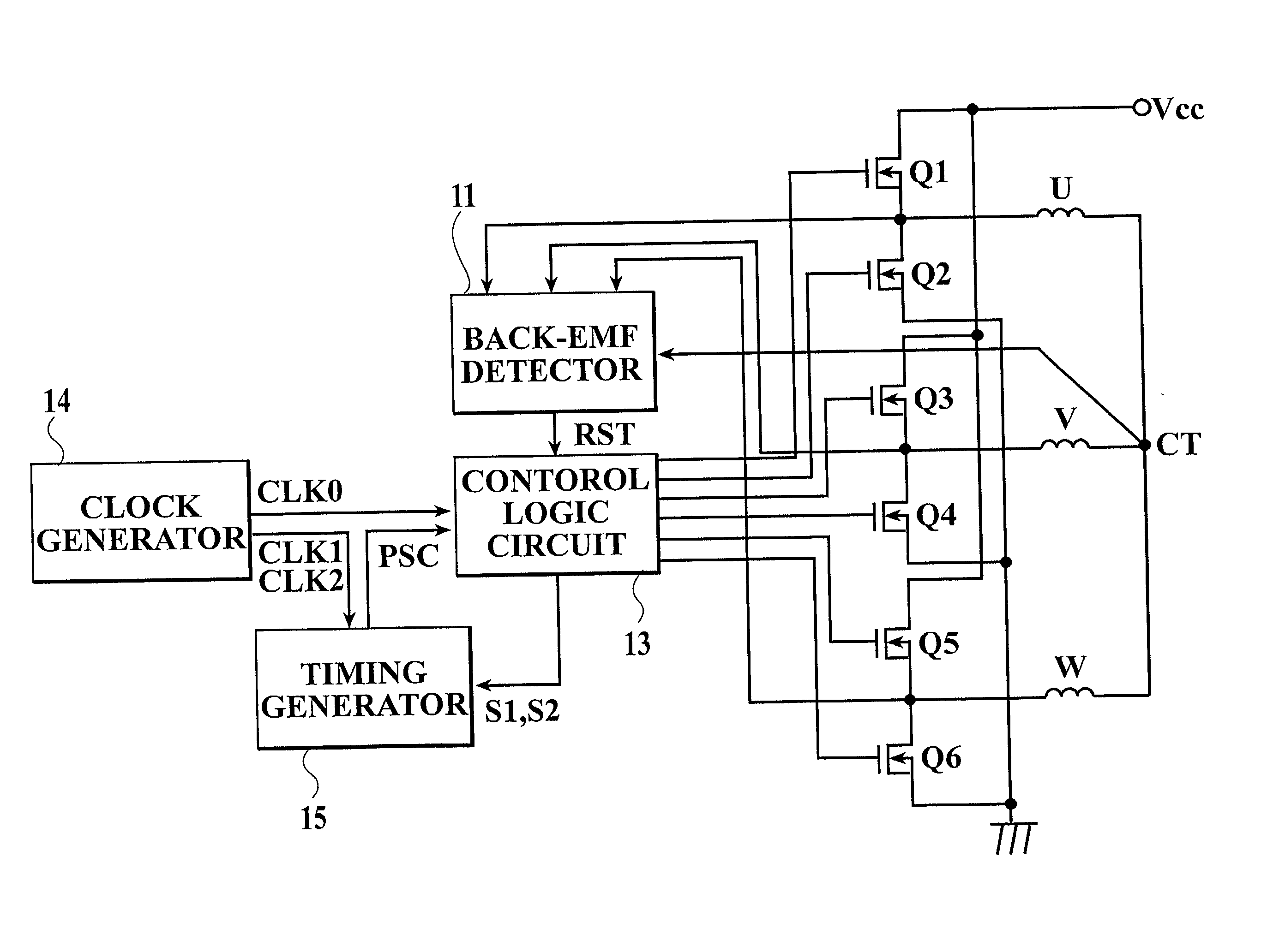
[0036] FIG. 4 is a block diagram showing an exemplary construction of an effective circuit for driving a three-phase full-wave drive brushless motor, to which a present invention is applied.
[0037] The reference characters "U", "V" and "W" denote three phase stator windings which are wound on a stator core of the three-phase full-wave drive brushless motor, and "Q1" to "Q6" denote output transistors for supplying a driving current to the U-phase, V-phase and W-phase stator windings. Further, the reference numeral "11" denotes a back-EMF (back electromagnetic force) detector for detecting a position of a rotor magnet of the three-phase full-wave drive brushless motor rotating on the basis of a zero cross point of a back-EMF generated in a non current-carrying phase of the three phase stator windings of the three-phase full-wave drive brushless motor, "13" denotes...
PUM
 Abstract
Description
Claims
Application Information
 - R&D
- Intellectual Property
- Life Sciences
- Materials
- Tech Scout
- Unparalleled Data Quality
- Higher Quality Content
- 60% Fewer Hallucinations
Browse by: Latest US Patents, China's latest patents, Technical Efficacy Thesaurus, Application Domain, Technology Topic, Popular Technical Reports.
© 2025 PatSnap. All rights reserved.Legal|Privacy policy|Modern Slavery Act Transparency Statement|Sitemap|About US| Contact US: help@patsnap.com


