Lens assembly for endoscopic lens system

a technology of endoscopic lens and lens assembly, which is applied in the field of lenses, can solve the problems of affecting the quality of endoscopic observation,

Inactive Publication Date: 2002-12-12
FUJI PHOTO OPTICAL CO LTD
View PDF6 Cites 65 Cited by
  • Summary
  • Abstract
  • Description
  • Claims
  • Application Information

AI Technical Summary

Problems solved by technology

Since the first lens is fitted in an exposed state on a rigid tip end section of an endoscopic insertion instrument, its exposed outer surface is often contaminated by deposition of body fluids or other contaminants which degrade observing picture images to a considerable degree.
Fogging even in a slight degree of a center portion of the first lens element causes considerable degradations to picture images and makes the endoscopic observation difficult because light fluxes necessary for forming images are concentrated in the center portion.
A distal end portion of an endoscopic insertion instrument can be cooled off quickly due to other reasons, resulting in fogging of and condensation of moisture on the first lens element of the objective lens system.
However, considering the severe conditions in which endoscopes are used, that is, considering repeated washing, disinfection and heated sterilization of endoscopes in use, it appears almost impossible for an adhesive or seal material to prevent moisture from creeping into a lens tube of an objective lens system over a long period of time.
However, due to a difference

Method used


Image

  • Lens assembly for endoscopic lens system
  • Lens assembly for endoscopic lens system
  • Lens assembly for endoscopic lens system

Examples


Embodiment Construction

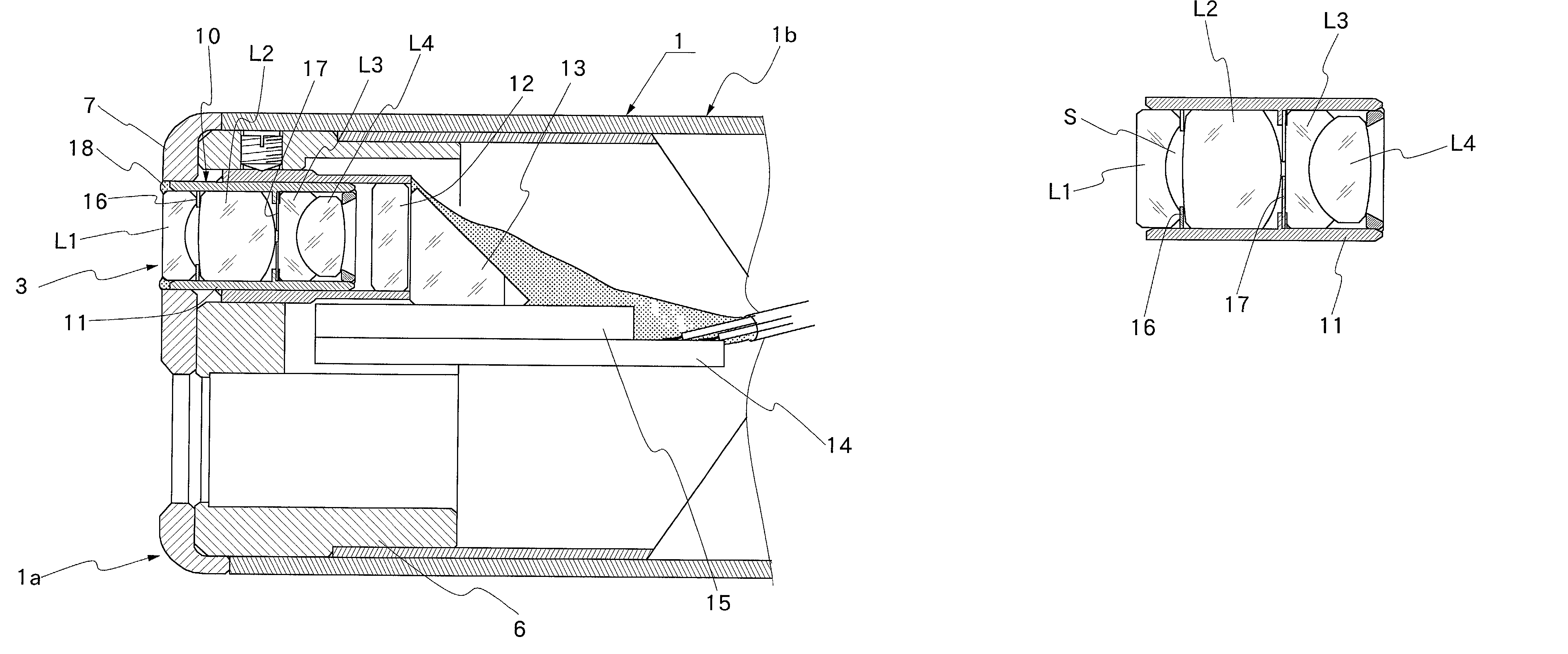
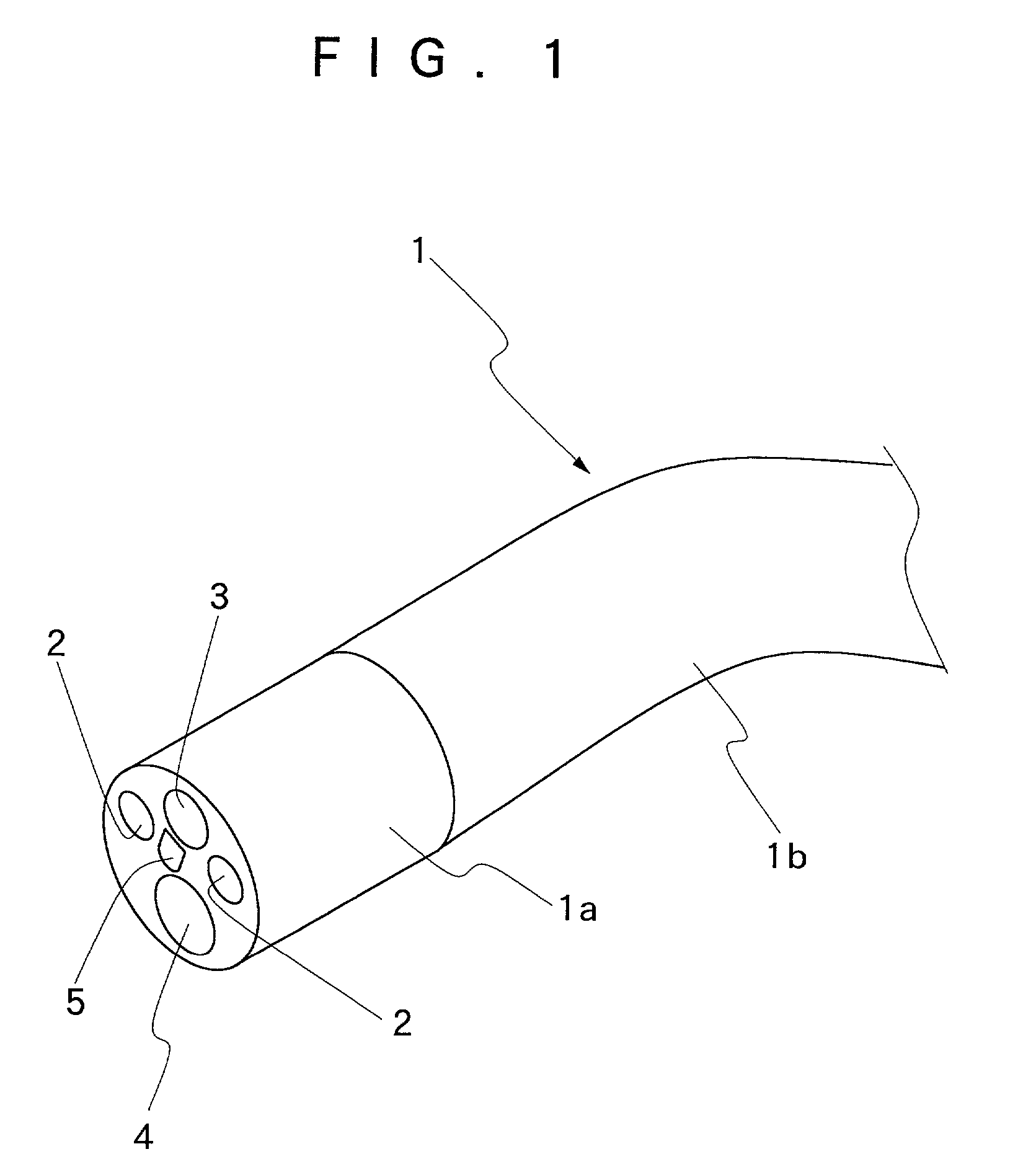
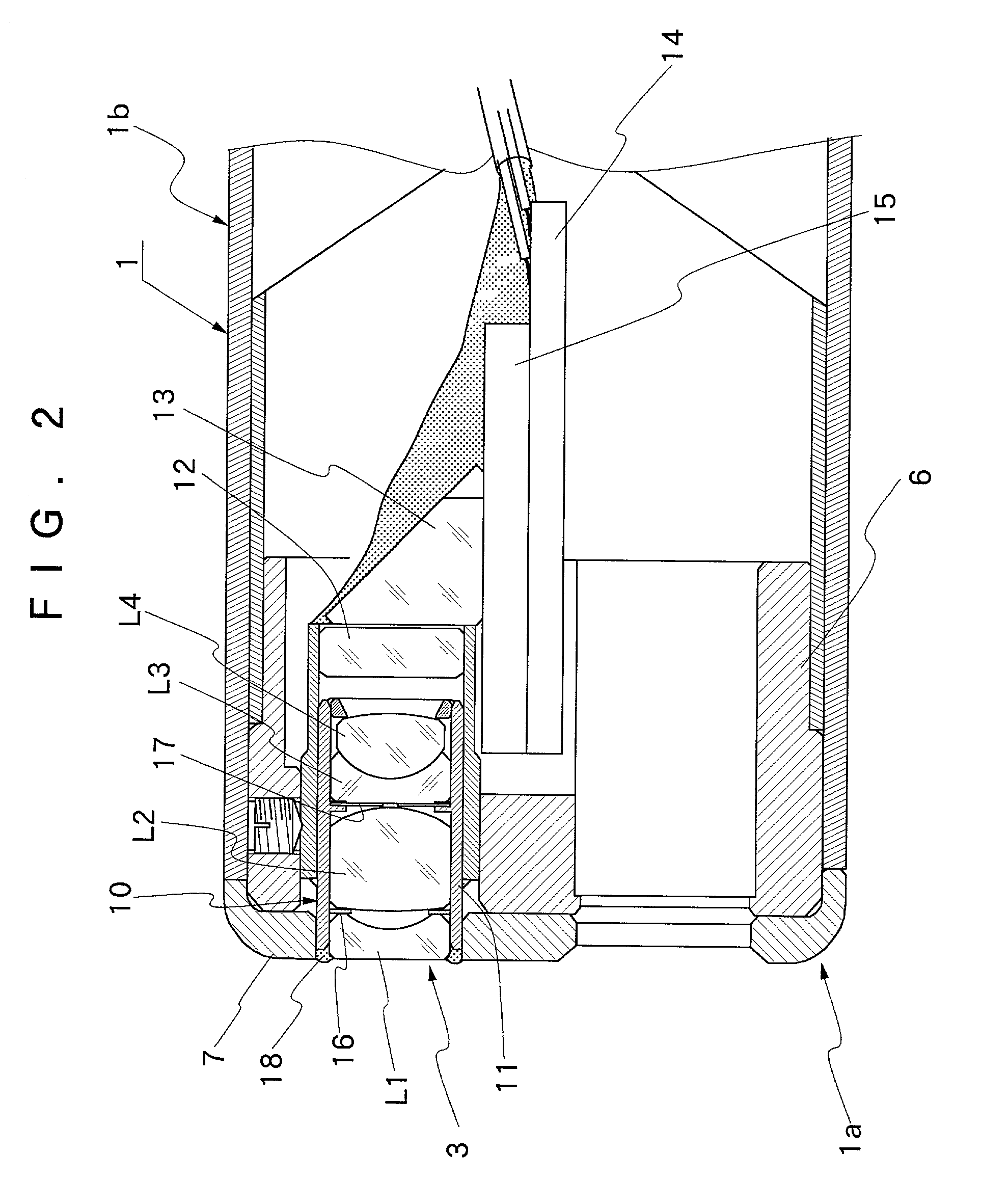
[0035] Hereafter, the present invention is described more particularly by way of its preferred embodiments with reference to the accompanying drawings. Firstly, shown schematically in FIG. 1 is a tip end portion of an endoscopic insertion instrument. In this figure, indicated at 1 is an insertion instrument to be introduced into a body cavity. At the fore distal end, the insertion instrument 1 is provided with a rigid tip end section 1ahaving a rigid structure for supporting endoscopic observation and illumination means thereon. Through an angle section 1b of a predetermined axial length, the proximal end of the rigid tip end section 1a is connected to an elongated flexible main body, which is connected to a manipulating head assembly of the endoscope although not shown in the drawings. The angle section 1b is provided for turning the rigid tip end section 1a into a desired direction. Opened in a fore end face of a casing of the rigid tip end section 1a are an illumination window 2 ...


PUM


Abstract

An optical lens assembly containing a plural number of lens elements for an optical system to be incorporated into a tip end portion of an endoscopic insertion instrument. Of a plural number of lenses which constitute an optical system, a metal film layer is formed on confronting outer peripheral surface portions of at least two adjacently located lenses, outside respective effective lens areas, and the two adjacently located lenses are assembled and fixedly bonded together by applying solder to the outer peripheral surface portions with a metal film layer.

Description

[0001] 1. Field of the Art[0002] This invention relates to a lens assembly which is particularly suitable for use as an optical objective lens system on an endoscopic insertion instrument.[0003] 2. Prior Art[0004] For insertion into a body cavity, endoscopes generally have an insertion instrument which is extended out on the front side of a manipulating head assembly. An illumination means and an endoscopic observation means are incorporated into a distal end portion of the insertion instrument for endoscopic observation and examination of intracavitary sites of interest. The illumination means includes a light guide which is constituted by a bundle of fiber optics to transmit illumination light to a distal end of the insertion instrument from a light source to which an endoscope is disconnectibly connected. A light emitting end of the light guide is disposed in an illumination window which is provided on a rigid tip end section of the insertion instrument. An illumination lens is f...

Claims


Application Information

Patent Timeline
IPC IPC(8): A61B1/00G02B23/26G02B7/02G02B23/24
CPCG02B7/02G02B23/243G02B7/025
Inventor WATANABE, JOJISAKAMOTO, KAZUHIROMIURA, NOBUYUKIYAMATAKA, SHUICHIKUBOYA, HIROSHIKOBAYASHI, TADASU
Owner FUJI PHOTO OPTICAL CO LTD
Why Eureka
Try Eureka