
Clutch

Inactive Publication Date: 2002-12-26
KTM SPORTMOTORCYCLE AG
View PDF5 Cites 6 Cited by
  • Summary
  • Abstract
  • Description
  • Claims
  • Application Information

AI Technical Summary

Benefits of technology

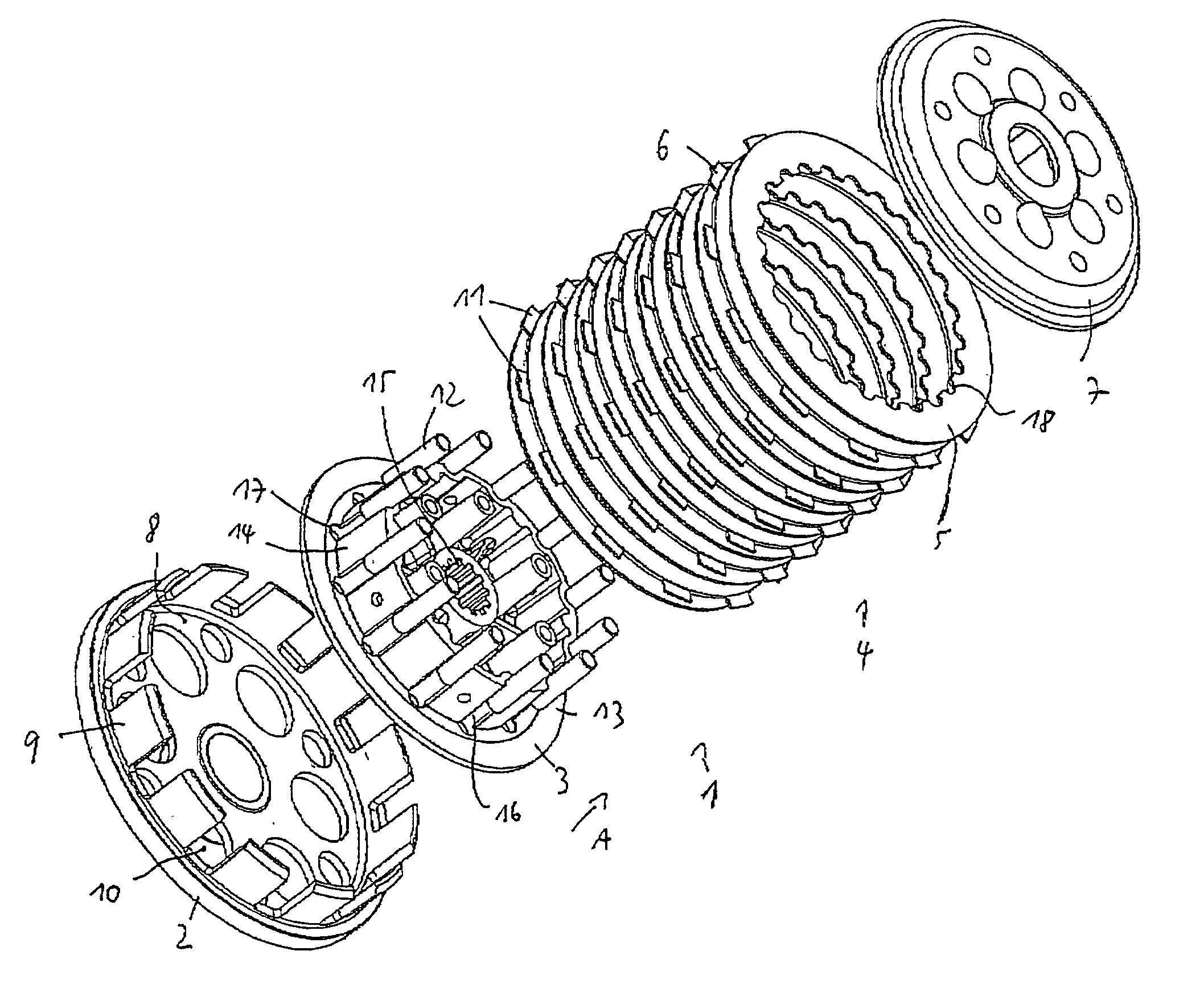
[0011] This means, in other words, that a torque transmission takes place between the clutch hub and the pressure discs via interposed movable driver elements, against which the clutch hub and the pressure discs rest. At the same time these driver elements may be so designed that they increase the effective surface for positive torque transmission between themselves and the clutch hub, thereby reducing the surface pressure occurring at the clutch hub, so that the steel plates may be made smaller (narrower), resulting in an overall reduction in the axial length of the clutch.
[0013] According to a further development of the invention it is here provided that the driver elements are tubular. bodies, mounted so as to be capable of sliding in the direction of the longitudinal axis of the clutch hub. With this design, when the clutch is opened and / or closed, the driver elements are able to move relative to the clutch hub and / or the pressure discs in such a way that, on the one hand, an optimal contact pattern for the particular conditions is established between the force transmission partners, while on the other hand the ability to modulate the clutch is distinctly improved as compared with known clutches.
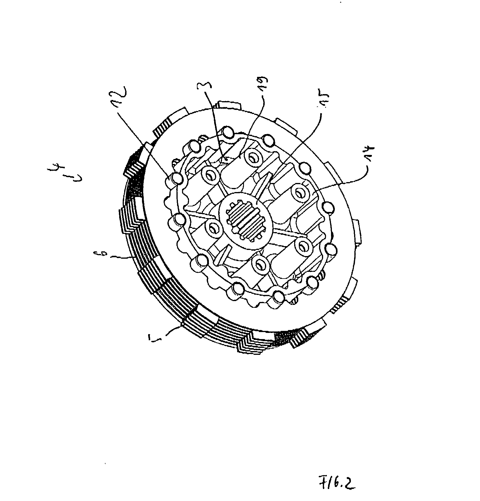
[0016] The clutch hub provided according to the invention may be made from a weight-saving light metal alloy. On its outer periphery side it has circular-segment-shaped recesses running in the axial longitudinal direction of the clutch hub, into which the driver elements--made for example of steel--may be inserted. These elements have a diameter such that the surface pressure values prevailing between the clutch hub and the driver elements are not critical. The pressure discs of the clutch provided according to the invention may also be made of steel or a steel alloy and are not in direct physical connection with the clutch hub, but instead lie only on the driver elements. Consequently, on account of the steel-on-steel material pairing which then exists, narrow or thin pressure discs are possible so that the clutch may be made short, viewed in its axial longitudinal direction. This short construction also leads to a reduction in the rotational moment of inertia of the clutch, therefore leading altogether to an internal combustion engine design which reacts very willingly. The clutch provided according to the invention also stands out for the fact that, compared with known clutches, its wearing behaviour is very much more favourable. Also, owing to the wide surfaces available for torque transmission between the clutch hub and the driver elements, good damping is obtained, the modulation of the clutch noticeable for the driver of the motorcycle thus equipped is markedly enhanced, since chatter marks or the like no longer occur, and in addition machining of the clutch basket is simplified since the extension angles required on known clutches between the clutch hub and the steel plates are dispensed with.

Problems solved by technology

This construction sets tight limits for any further reduction in size of the clutch, which are fallen below only by clutches used in racing, in which a short clutch life is taken into account.
These depressions then make it extremely difficult for any movement of the steel plates relative to the clutch hub in the clutch hub axial direction, so that the clutch no longer opens properly and therefore no longer separates cleanly.

Method used


Image

  • Clutch
  • Clutch
  • Clutch

Examples


Embodiment Construction

)

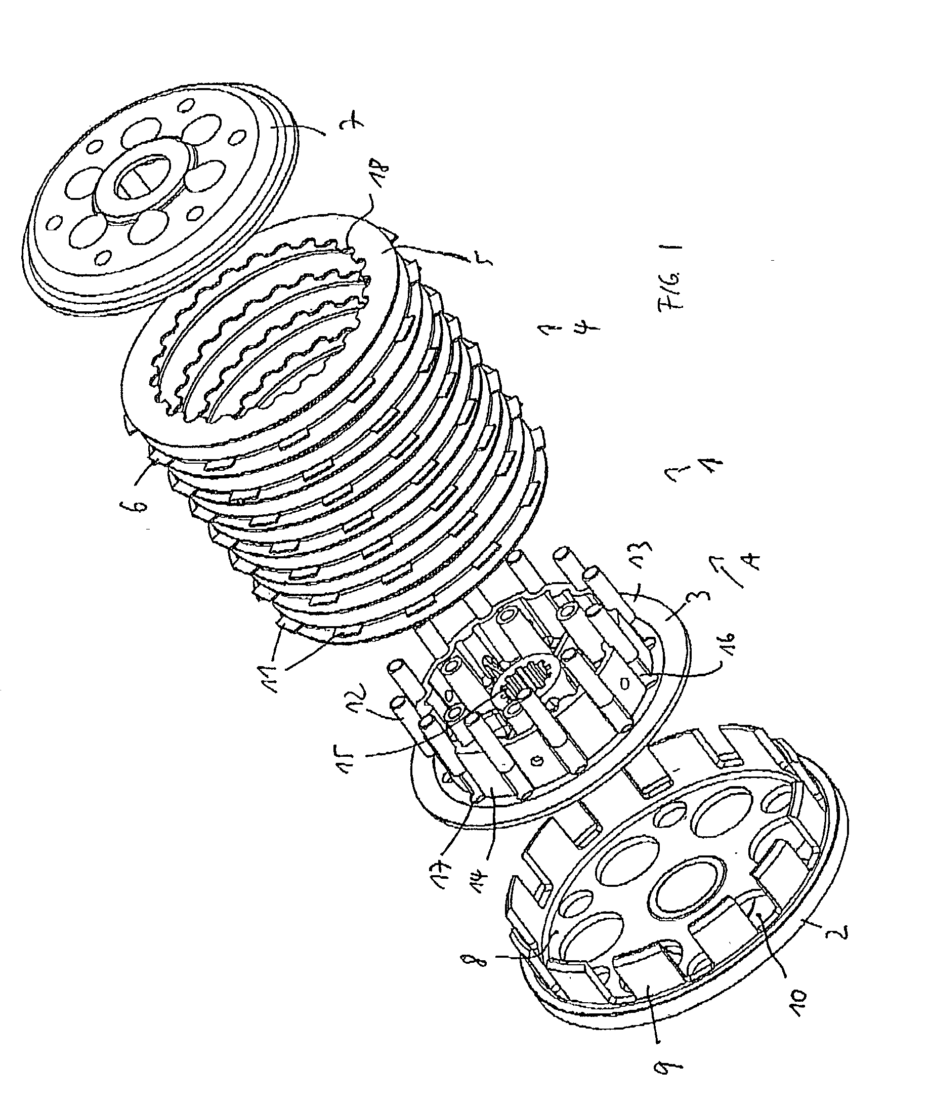
[0020] FIG. 1 of the drawing shows in a perspective exploded view an embodiment of a clutch according to the present invention in which, to simplify the illustration, known components such as for example clutch compression springs, spring retaining screws, the clutch push rod and the like have been omitted.

[0021] The clutch 1 according to the present invention has a clutch basket 2 which is designed to accommodate a clutch hub 3, on which a clutch disc assembly of clutch discs 4 in the form of pressure discs 5 and friction discs 6 may be assembled. A pressure plate 7 is placed on top of the clutch disc assembly and presses on the disc assembly by means of clutch compression springs, which are not illustrated, in order to generate frictional resistance between the individual discs.

[0022] In a manner not shown in detail, the clutch basket 2 may be connected to the primary drive of a drive motor, in the form for example of a motorcycle engine, to supply to the clutch basket 2 an outpu...


PUM


Abstract

A clutch (1) with a multiplicity of clutch discs (5, 6) in the form of friction discs (6) and pressure discs (5), arranged between a clutch basket (2) and a clutch hub (3), and with means of positive torque transmission between the clutch discs (5, 6), the clutch basket (2) and with the clutch hub (3), wherein the means of torque transmission between the clutch hub (3) and the pressure discs (5) are provided by movable driver elements (12).

Description

[0001] 1. Field of the Invention[0002] The present invention relates to a clutch with a multiplicity of clutch discs in the form of friction discs and pressure discs.[0003] 2. Description of the Related Art[0004] The clutch referred to here is therefore a multi-plate clutch with several friction discs and pressure discs, and may be used as an oil bath multi-plate clutch for a motorcycle, between the drive motor and the gearbox of the motorcycle.[0005] A motorcycle clutch of this type usually has a clutch basket, which is connected to the primary drive of the drive motor to transmit the drive torque, and a clutch hub which rests by an internal gearing on the clutch shaft of the motorcycle gearbox. By opening and closing the clutch, the torque transmission from the motor to the gearbox may be interrupted or established.[0006] To simplify mechanical finishing and to reduce the weights to be moved, the clutch hub is usually made from an aluminium alloy and has on its outer periphery a g...

Claims


Application Information

Patent Timeline
IPC IPC(8): F16D13/52F16D13/64
CPCF16D13/648F16D13/52
Inventor LINHUBER, MAXSCHNAPPINGER, PATRIZIA
Owner KTM SPORTMOTORCYCLE AG
Learn More