Interference signal removal system

a signal removal and interference technology, applied in the direction of amplitude demodulation, line-faults/interference reduction, pulse technique, etc., can solve the problem of increasing the probability of dsss signals encountering interference, natural interference between signals, and inability to obtain interference signal suppressing effects

Inactive Publication Date: 2002-12-26
KOKUSA ELECTRIC CO LTD
View PDF8 Cites 81 Cited by
  • Summary
  • Abstract
  • Description
  • Claims
  • Application Information

AI Technical Summary

Problems solved by technology

Since the two systems conduct wireless communication using the same frequency band and are allowed to interfere systematically, the signals naturally interfere with each other.
In FHSS, interference between signals transmitted by different transmitters using different hopping patterns is unlikely to cause a problem because the probability of the same frequency being used at the same time is low.
It may therefore become impossible to obtain an interference signal suppressing effect.
The probability of DSSS signals encountering interference is therefore increasing.
Other instances in which interference may become a problem include interference occurring in adjacent frequency bands between W-CDMA (Wideband-Code Division Multiple Access) communication signals and PHS (Personal Hand phone System) communication signal, interference occurring between 2.4 GHz band wireless LAN (IEEE 802.11) broadband signals and Bluetooth narrow-band signals, interference occurring owing to frequency band sharing between CDMA communication signals and TDMA (Time Division Multiple Access) or FDMA (Frequency Division Multiple Access) communication signals, and interference caused by unpredictable extraneous waves.
As explained above, in this type of wireless communication, interference may occur within the broad frequency band whose frequencies are approved and used for communication, owing to unintentional mixing therewith of other (i.e., other than CDMA) narrow-band signals and the like.
When the signals of this type exceed the level of interference by noise and the like envisioned at the time of system design, the number of bit errors increases and the quality of receiver reception is markedly degraded.
Unless the CDMA receiver can remove the FM signal etc. from the received signal, however, it and the spread signal will interfere with each other to increase the number of bit errors and degrade the reception quality.
As shown in FIGS. 18(c) and 18(d), in the case of interference signals that vary intensely like TDMA signals, the conventional interference signal removal system cannot, merely by speeding up the update rate of the control coefficient h(t+1), thoroughly remove interference signals, because sufficient time for interference signal estimation cannot be obtained at the beginning of interference signal reception.
Moreover, a configuration that updates the control coefficient h(t+1) for interference signal estimation and extraction at high speed is not practical from the aspect of system feasibility.
Although a method that does not sequentially update the control coefficient h(t+1) and operates the filter using a constant control coefficient h(t+1) even when no interference signal is present is conceivable, this method is disadvantageous because the effect of the interference signals on the received signal increases and reception quality degenerates when interference is received in multiple frequency bands.
As is clear from the foregoing discussion of the prior art, conventional interference signal removal systems cannot achieve sufficient interference signal removal accuracy when removing interference signals that vary intensely like TDMA signals.
Moreover, conventional interference signal removal systems have not given adequate attention to techniques for efficient removal of interference signals that appear repeatedly in the manner of TDMA signals.

Method used


Image

  • Interference signal removal system
  • Interference signal removal system
  • Interference signal removal system

Examples


example 4

[0237] Example 4 is shown in FIG. 7(a). In this Example 4, the interference signal removal system 11 is combinable with the interference signal system 12 of this embodiment and is capable of utilizing the method described earlier with respect to the present invention.

[0238] The interference signal removal system illustrated in FIG. 6(a) receives an RF band received signal as input. The received signal is amplified by a low noise amplifier (LNA) D1, the amplified signal is amplified by a variable gain amplifier (VGA) D2, the amplified input signal is filtered by a magnetostatic wave filter D3, and the filtered input signal is adjusted in level and output by a level adjuster D4. Further, in this interference signal removal system, the output from the variable gain amplifier D2 is detected by a detector D5 and the detection result is used to control the variable gain amplifier D2.

[0239] FIG. 6(b) shows the configuration of the magnetostatic wave filter D3. The magnetostatic wave filter...

second embodiment

[0249] the interference signal removal system according to this invention will now be explained.

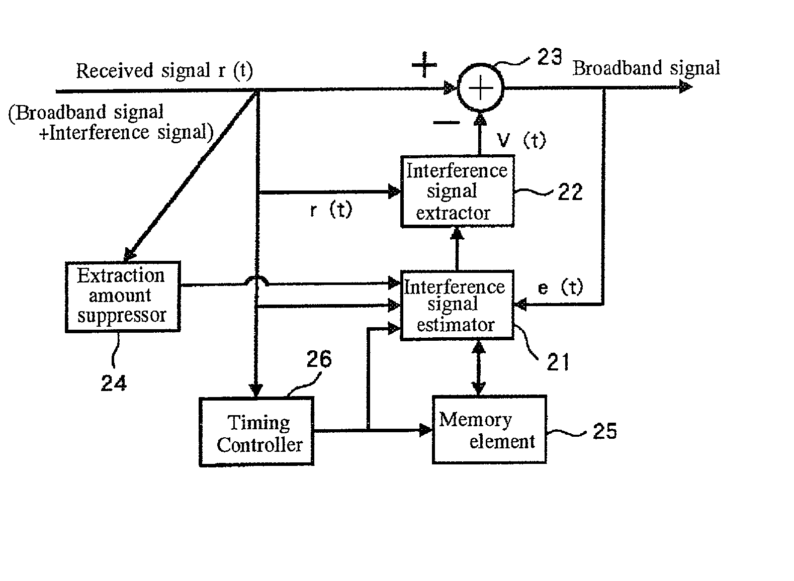
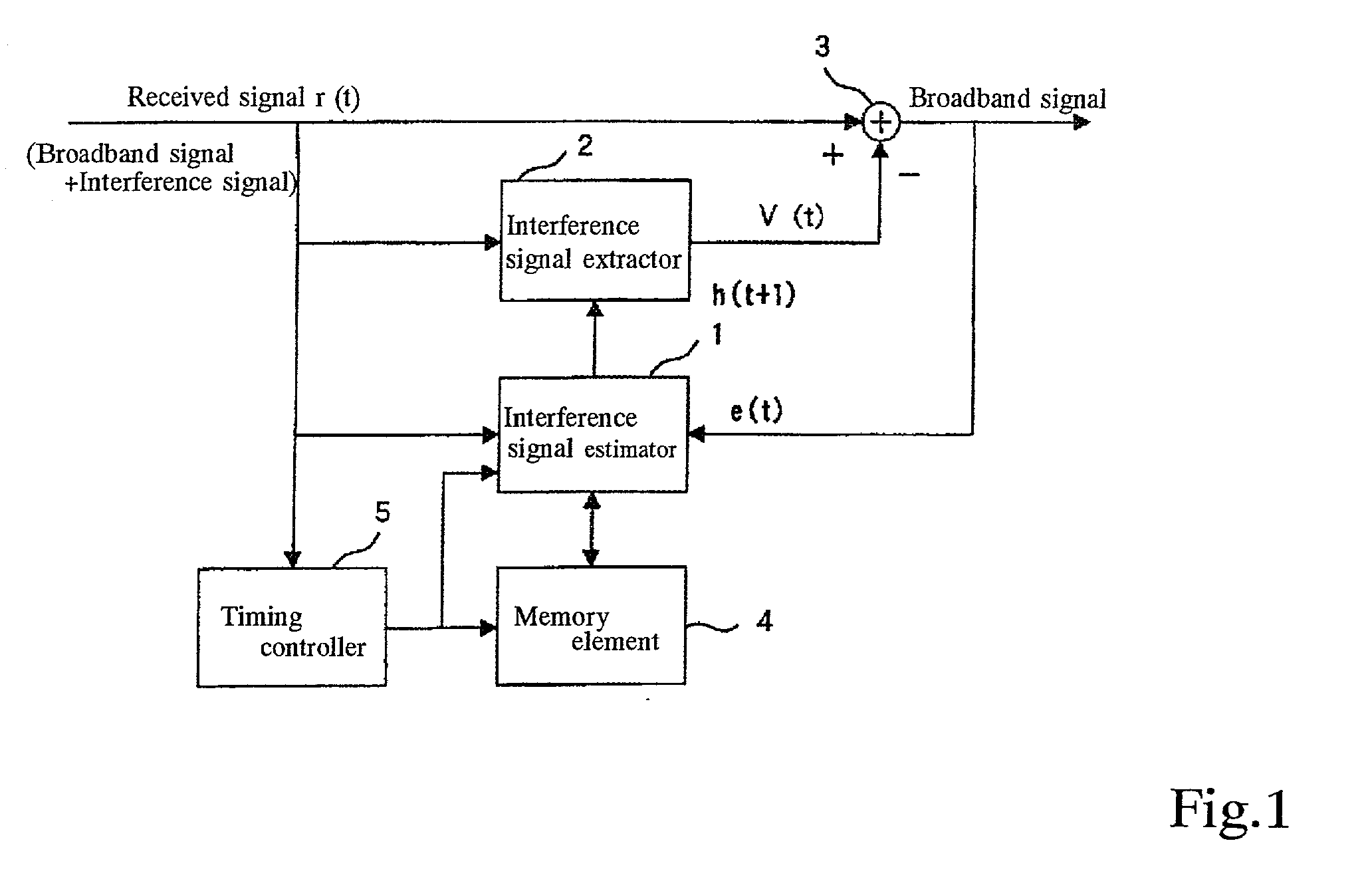
[0250] This embodiment will be explained with regard to the case where the present invention is applied to an interference signal removal system that, similarly to the interference signal removal systems taught by Japanese Patent Application Nos. 2000-3284437 and 2000-328740, removes an interference signal from an input signal containing a broadband desired signal and a narrow-band interference signal by extracting the interference signal contained in the input signal while suppressing the amount of the extraction based on the input signal, and removes the extracted interference signal from the input signal.

[0251] FIG. 9 shows an example of the configuration of the second embodiment of the interference signal removal system according to the present invention. The illustrated interference signal removal system is equipped with an interference signal estimator 21, an interference signal ext...


PUM


Abstract

An interference signal removal system includes interference signal estimating means for estimating an interference signal contained in a received signal based on the received signal and a result obtained by removing an interference signal from the received signal, interference signal removing means for removing from the received signal the interference signal estimated by the interference signal estimating means; and interference signal estimation controlling means for storing the interference signal estimation result of the interference signal estimating means in memory and controlling the interference signal estimation by the interference signal estimating means so as to estimate an interference signal contained in the received signal based on a past interference signal estimation result stored in memory.

Description

[0001] 1. Field of the Invention[0002] This invention relates to an interference signal removal system for removing a narrow-band interference signal from a received signal that contains a narrow-band interference signal and a desired broadband signal and varies periodically in received power level, particularly to such a system enabling efficient interference signal removal.[0003] 2. Description of the Prior Art[0004] A received signal received by a receiver may, for example, contain not only the signal to be received (desired signal) but also an accompanying signal that interferes with the desired signal (interference signal).[0005] An explanation will be given regarding broadband desired signals and narrow-band interference signals, taking the wireless LAN (Local Area Network) of IEEE 802.11 as an example.[0006] It should be noted that the meanings of the terms "broadband" and "narrow-band" are relative. Specifically, a signal whose exclusive bandwidth is considerably broad in co...

Claims


Application Information

Patent Timeline
Patent Type & Authority Applications(United States)
IPC IPC(8): H04B1/10
CPCH04B1/7101H04B1/1036
Inventor TAKADA, MASATOSHI
Owner KOKUSA ELECTRIC CO LTD
Why Eureka
Try Eureka