
Transflective electro-optical device and electronic apparatus

a technology of electro-optical devices and electronic devices, applied in non-linear optics, identification means, instruments, etc., can solve the problems of low optical efficiency of color reflective electro-optical devices, difficult to address or solve, and abnormal color tones in color transmissive display

Inactive Publication Date: 2003-01-02
SEIKO EPSON CORP
View PDF7 Cites 13 Cited by
  • Summary
  • Abstract
  • Description
  • Claims
  • Application Information

AI Technical Summary

Benefits of technology

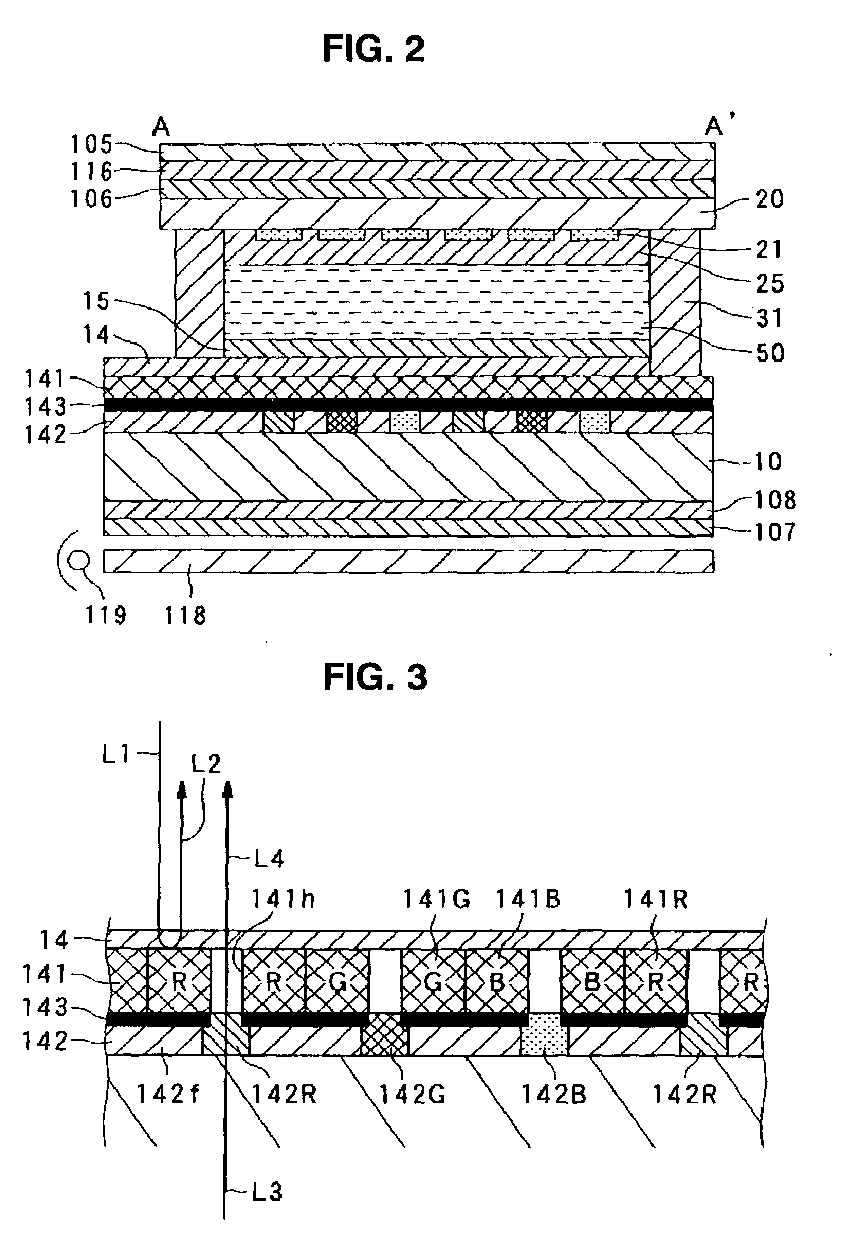
[0015] As a result, according to the transflective electro-optical device of the present invention, by using the selective-reflection type first color filter, the optical efficiency therein is high in a bright place, and hence, a bright, color reflective display can be created. In a dark place, regardless of the presence of the first color filter, by the second color filter, a color transmissive display can be created in each pixel as with the case in which a color reflective display is created.

Problems solved by technology

However, this type of color filter has been formed so that each pixel selectively transmits light in a predetermined wavelength range and selectively absorbs light outside of that range, and hence, the optical efficiency for this type of color reflective electro-optical device is basically low.
Accordingly, when a display device is formed so that the color tones are normally displayed in color reflective display, a problem may arise in that the color tones are abnormally displayed in color transmissive display.
As a result, according to any of the techniques described above, there has been a problem, which is difficult to address or solve, in that a color display having normal color tones and a bright, color reflective display cannot be compatible with each other in a transflective electro-optical device.

Method used


Image

  • Transflective electro-optical device and electronic apparatus
  • Transflective electro-optical device and electronic apparatus
  • Transflective electro-optical device and electronic apparatus

Examples


first embodiment

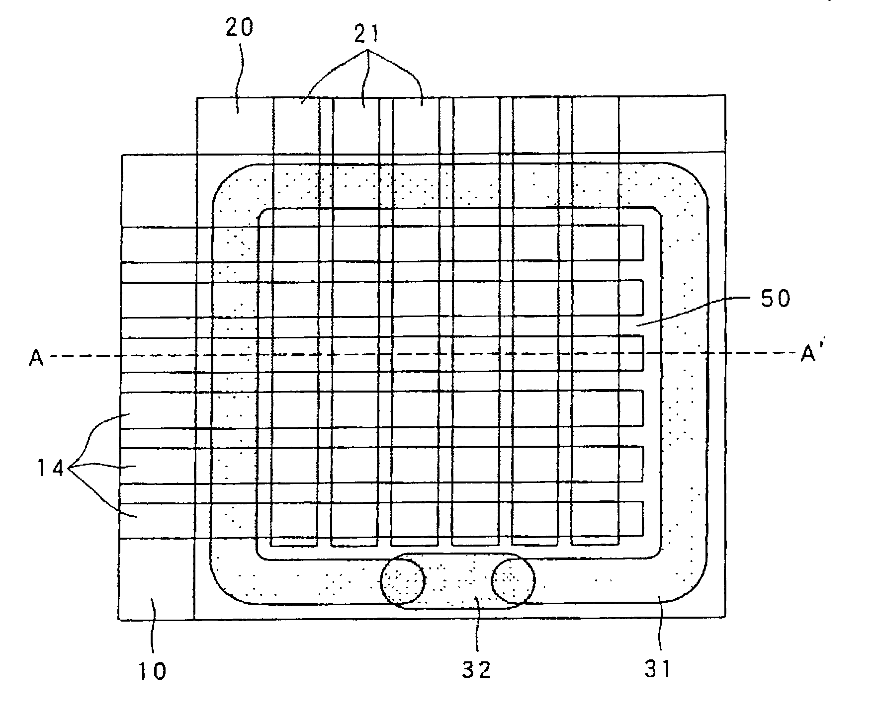
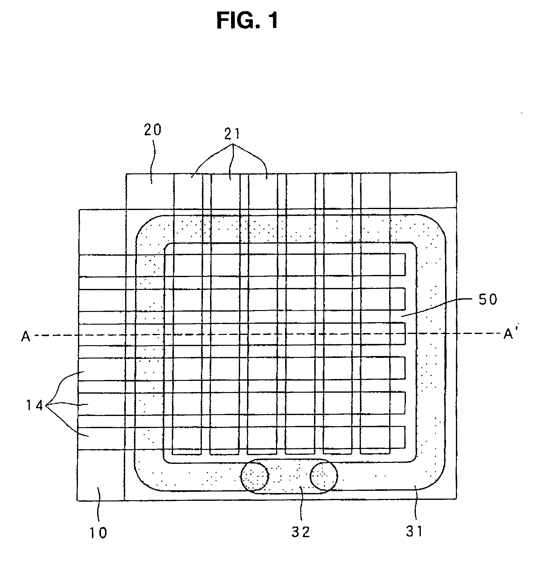
[0062] In FIGS. 1 and 2, the transflective liquid crystal device of the first embodiment includes a transparent first substrate 10, a transparent second substrate 20 provided so as to be opposed to the first substrate 10, a liquid crystal layer 50 provided between the first substrate 10 and the second substrate 20, a plurality of transparent electrodes 14 in a stripe pattern provided at the first substrate 10 side so as to be opposed to the second substrate 20 (that is, at the upper side surface in FIG. 2), and an alignment layer 15 provided on the transparent electrodes 14. The transflective liquid crystal device has a plurality of transparent electrodes 21 in a stripe pattern provided on the second substrate 20 so as to be opposed to the first substrate 10 (that is, at the lower side surface in FIG. 2) and to intersect the transparent electrodes 14 and an alignment layer 25 provided on the transparent electrodes 21. The transflective liquid crystal device further includes a polari...

second embodiment

[0083] Next, a second embodiment of the present invention will be described with reference to FIG. 5. FIG. 5 is a cross-sectional view showing the structure of the second embodiment, and the same reference labels as with the first embodiment shown in FIG. 2 designate the same constituent elements in FIG. 5, and descriptions thereof will be omitted.

[0084] As shown in FIG. 5, in the second embodiment in which the structure is different from that of the first embodiment, the selective-transmission color filter 142 and the light-shielding film 143 are provided at the opposite side of the first substrate 10 from the liquid crystal layer 50. The rest of the structure is equivalent to that of the first embodiment.

[0085] According to the second embodiment, by the selective-transmission color filter 142 provided at the opposite side of the first substrate 10 from the liquid crystal layer 50, and the selective-reflection color filter 141 provided on the first substrate 10 at the liquid crysta...

third embodiment

[0086] Next, a third embodiment of the present invention will be described with reference to FIG. 6. FIG. 6 is a cross-sectional view showing the structure of the third embodiment, and the same reference labels as with the first embodiment shown in FIG. 2 designate the same constituent elements in FIG. 6, and descriptions thereof will be omitted.

[0087] As shown in FIG. 6, in the third embodiment in which the structure is different from that of the first embodiment, in place of the light guide plate 118 and the fluorescent tube 119, a plurality of point light sources 120 formed of an LED (light Emitting Diode), an El (Electro-Luminescence), or the like is dispersedly provided at positions opposed to the slits 141h of the selective-reflection color filter 141, that is, at positions opposed to the selective-transmission layers 142R, 142G, and 142B of the selective-transmission color filter 142. The rest of the structure is equivalent to that of the first embodiment.

[0088] According to ...


PUM

PropertyMeasurementUnit
diameteraaaaaaaaaa
widthaaaaaaaaaa
electro-opticalaaaaaaaaaa

Abstract

In an electro-optical device, such as a transflective liquid crystal device, color transmissive display having normal color tones is performed, and in addition, bright, color reflection display is also performed. The electro-optical device in accordance with the invention includes an electro-optical material provided between a first substrate and a second substrate, and display electrodes provided above the first substrate so as to be opposed to the second substrate. The electro-optical device further includes a first color filter having a selective-reflection region in each pixel that selectively reflects light in a predetermined wavelength range, and a light transmission region in each pixel that transmits light outside of the predetermined wavelength range; a light-shielding film provided so as to be opposed to the selective-reflection regions; and a second color filter having a selective-transmission region in each pixel that selectively transmits light in the predetermined wavelength range.

Description

[0001] 1. Field of Invention[0002] The present invention relates to transflective electro-optical devices which can interchangeably perform reflective display by using external light and transmissive display via light-source light. The invention also relates to an electronic apparatus provided with such a device.[0003] 2. Description of Related Art[0004] In a transflective electro-optical device, such as a transflective liquid crystal display device, reflective display is performed in a bright place by using external light while a light source is turned off. In a dark place, transmissive display is performed by using light emitted from the light source that is turned on. In particular, reflective display is performed by having incident external light reflected off of areas of a transflective film other than slits provided therein, which are used for light transmission, to the exterior of the device via an electro-optical material layer formed of liquid crystals or the like. On the o...

Claims


Application Information

Patent Timeline
Patent Type & Authority Applications(United States)
IPC IPC(8): G02F1/1335G09F9/00G09F9/30G09F9/35
CPCG02F1/133512G02F1/133514G02F1/133555G02F1/1335
Inventor IINO, SHOICHI
Owner SEIKO EPSON CORP
Learn More