Surface-mounted antenna and communications apparatus comprising same

a technology of communication apparatus and antenna, which is applied in the direction of resonant antennas, battery/fuel cell control arrangements, resonant antennas, etc. it can solve the problems of impedance matching, limit the use of high-dielectric constant materials, and not necessarily satisfactory in achieving sufficient miniaturization and reduction in height, so as to facilitate the miniaturization of the antenna substrate and expand the bandwidth

Inactive Publication Date: 2003-01-09
HITACHI METALS LTD
View PDF7 Cites 40 Cited by
  • Summary
  • Abstract
  • Description
  • Claims
  • Application Information

AI Technical Summary

Benefits of technology

0110] The current-feeding electrode 4 is formed on the side surface 1b of the substrate 1 on the side of the ground conductor 62, with the current-feeding end 140 of the current-feeding electrode 104 connected to the current-feeding wire 61, and the grounding end 142 connected to the ground conductor 62. A portion of a grounding electrode 32 connected to the radiation electrode 133, which is positioned near a corne

Problems solved by technology

However, because conventional surface-mounted antennas have characteristics, which are deteriorated with miniaturization and reduction in height, they are not necessarily satisfactory in achieving sufficient miniaturization and reduction in height.
However, there is actually a limit in the use of high-dielectric constant materials, and only dielectric substrates having dielectric constants .di-elect cons..sub.r of up to about 4 have been put into practical use, because a higher dielectric constant .di-elect cons..sub.r than the above level causes the problem of impedance matching.
Because input impedance at a current-feeding point is likely to change largely in a surface-mounted antenna having a high dielectric constant, it has become difficult to overcome the problem of

Method used


Image

  • Surface-mounted antenna and communications apparatus comprising same
  • Surface-mounted antenna and communications apparatus comprising same
  • Surface-mounted antenna and communications apparatus comprising same

Examples


Embodiment Construction

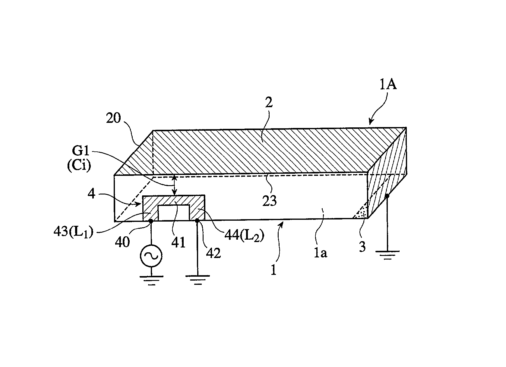
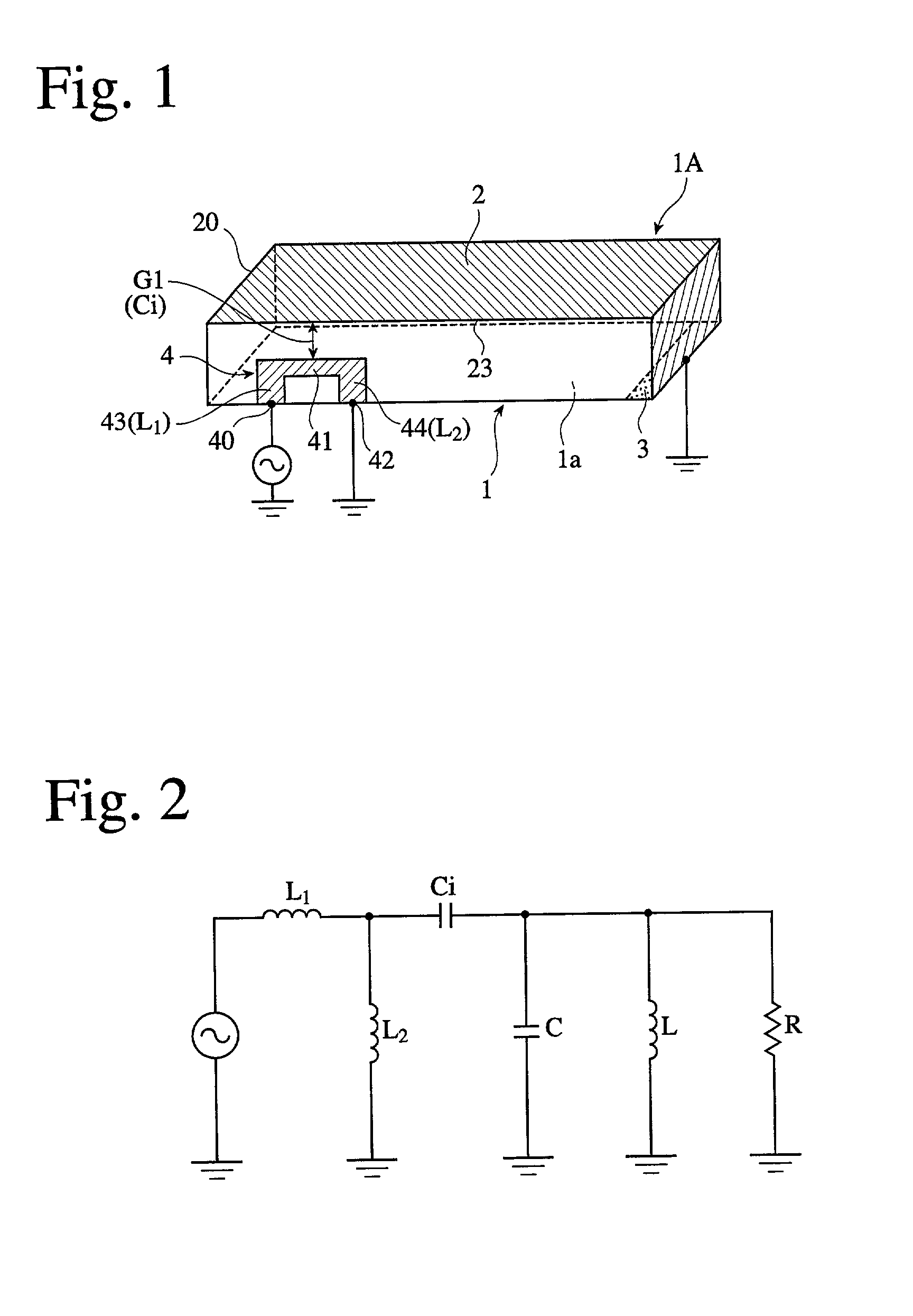
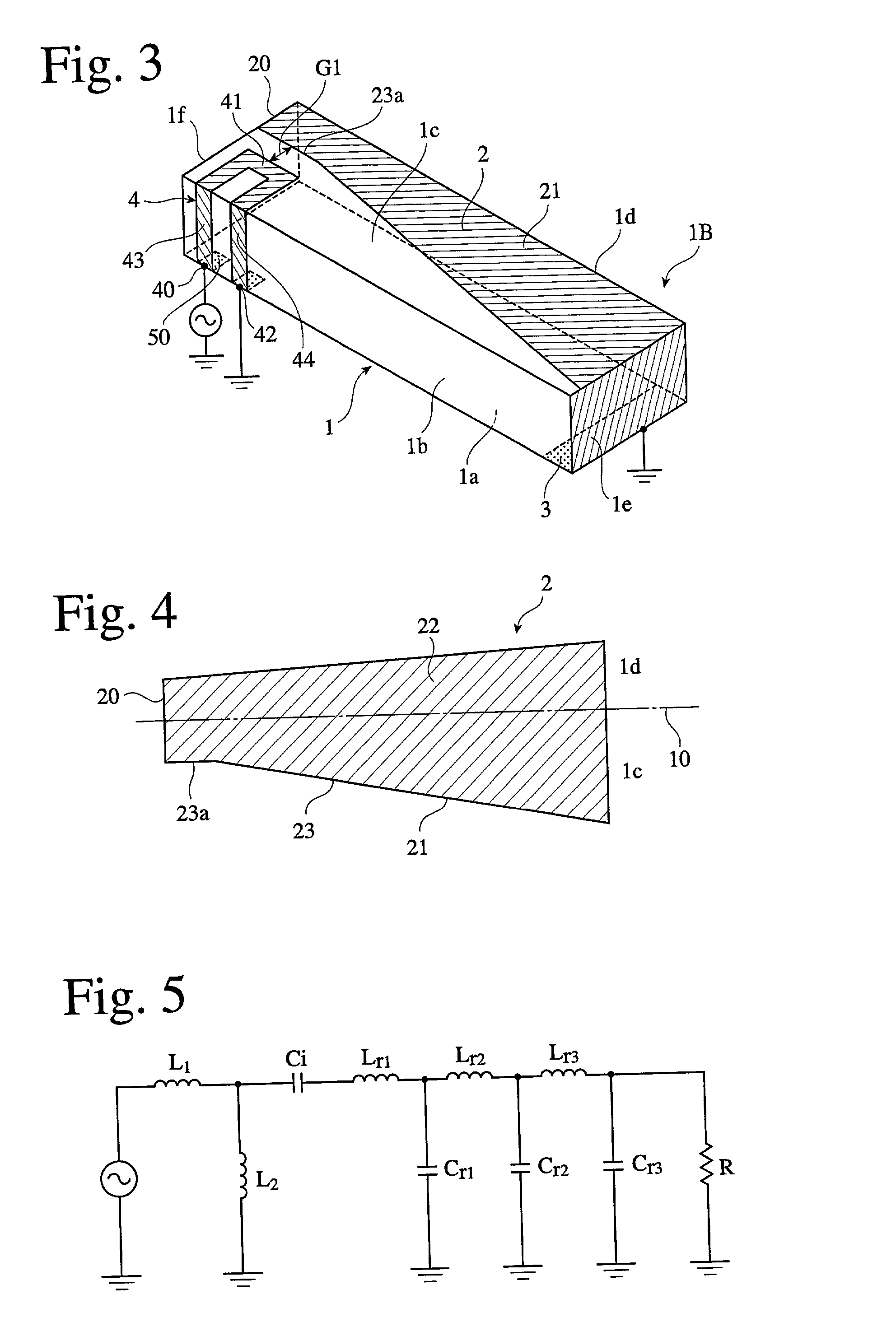
shown in FIG. 11 and Example 12 shown in FIG. 16, the characteristics of these antennas were tested. Also, the same antenna as shown in FIG. 3 except that part of the radiation electrode 2 is formed in a meandering shape as shown in FIG. 23 was used as Comparative Example 1, to test the characteristics of the antenna. An antenna substrate was formed by a dielectric ceramic having a dielectric constant .di-elect cons..sub.r of 21. The size of the substrate was 15 mm in length.times.3 mm in width.times.3 mm in thickness in Example 2 and Comparative Example 1, and 10 mm in length.times.3 mm in width.times.2 mm in thickness in Examples 7 and 12. With a propagation frequency having a center frequency of 1.575 GHz.+-.1 MHz, a bandwidth BW (MHz), an average gain (dBi) and directionality were measured at a voltage standing wave ratio (VSWR) of 2.

[0112] With the current-feeding terminal formed in one end portion of the antenna-mounted board connected to an input terminal of the network analy...


PUM


Abstract

A surface-mounted antenna comprising a substrate made of a high-dielectric constant material having a dielectric constant is inr of 6 or more, a ribbon-shaped radiation electrode having one end which is grounded and the other end which is open, a grounding electrode connected or capacitance-coupled to one end of the radiation electrode, and a current-feeding electrode in a portal shape formed on a side surface separate from the radiation electrode with a gap; the current-feeding electrode having a current-feeding portion at one end, a grounding portion at the other end, and a portion substantially in alignment with the radiation electrode between them; and the length of the aligning portion, a gap width or a portal shape being able to be properly set such that capacitance owned by the current-feeding electrode and inductance can be adjusted for easily achieving impedance matching.

Description

[0001] The present invention relates to a small antenna comprising a substrate made of dielectric or magnetic materials such as ceramics, resins, etc., particularly to a surface-mounted antenna having an impedance-matching function in its current-feeding electrode, and a communications apparatus comprising such a surface-mounted antenna.[0002] Surface-mounted antennas are used for global positioning systems (GPS), local area networks (wireless LAN), etc. with carrier waves in a GHz band. The miniaturization of mobile gears proceed at a dramatic speed, and the surface-mounted antennas are required to be small with reduced height, have good radiation efficiency without directionality, and further be operable in a wide band. However, because conventional surface-mounted antennas have characteristics, which are deteriorated with miniaturization and reduction in height, they are not necessarily satisfactory in achieving sufficient miniaturization and reduction in height.[0003] In general...

Claims


Application Information

Patent Timeline
IPC IPC(8): H01Q1/24H01Q1/36H01Q1/38H01Q9/04H01Q9/40H01Q9/42
CPCH01Q1/243H01Q1/38H01Q9/0421Y02T10/70B62K5/027B60L50/66B60L58/12B62K2202/00B62K2204/00B60L2200/12
Inventor AOYAMA, HIROYUKIKIKUCHI, KEIKOTAKAKI, YASUNORIHAGIWARA, HIDETOSHI
Owner HITACHI METALS LTD
Why Eureka
Try Eureka