
Systems and methods for generating binary clustered, irrational halftone dots

a technology of clustering and halftone dots, applied in the field of system and method for generating binary irrational halftone dots, can solve the problems of the inability to avoid such moir patterns or noise in the resulting image when electronic registration, and the inability to accurately capture the correct image density. the effect of enhancing the utility of electronic registration

Inactive Publication Date: 2003-01-09
XEROX CORP
View PDF4 Cites 19 Cited by
  • Summary
  • Abstract
  • Description
  • Claims
  • Application Information

AI Technical Summary

Benefits of technology

[0015] Electronic registration refers to adjusting the spatial positions on the image substrate that the image structures, such as the halftone dots, will be placed by the image forming apparatus to compensate for any physical offsets in the image forming apparatus that would otherwise result in misregistration between the color separation layers. That is, rather than physically, i.e., mechanically, ensuring that the color separation layers are precisely aligned, the various offsets between the various color separation layers are measured. The electronic data is then electronically adjusted to change the spatial locations of the resulting image structures, so that the resulting image structures of each corresponding color separation layer are properly aligned. Being able to move or warp an image structure such as halftone dots without causing moir patterns or noise that detract from the image quality will increase the utility of electronic registration.
[0016] Dithering the edges of an image structure, such as a halftone dot, that extend horizontally along the fast scan direction can accurately capture the correct image density to be represented by the image structure, such as the halftone dot. However, such high-frequency structures along the edges of the image structure, such as the halftone dot, often, if not invariably, result in artifacts, such as moir patterns or noise, when the halftone dots are moved to accomplish electronic registration. In particular, dithering the edges of the image structures, such as the halftone dots, to ensure the proper tone is reproduced generally renders it impossible to avoid such moir patterns and / or noise in the resulting image when electronic registration is used.
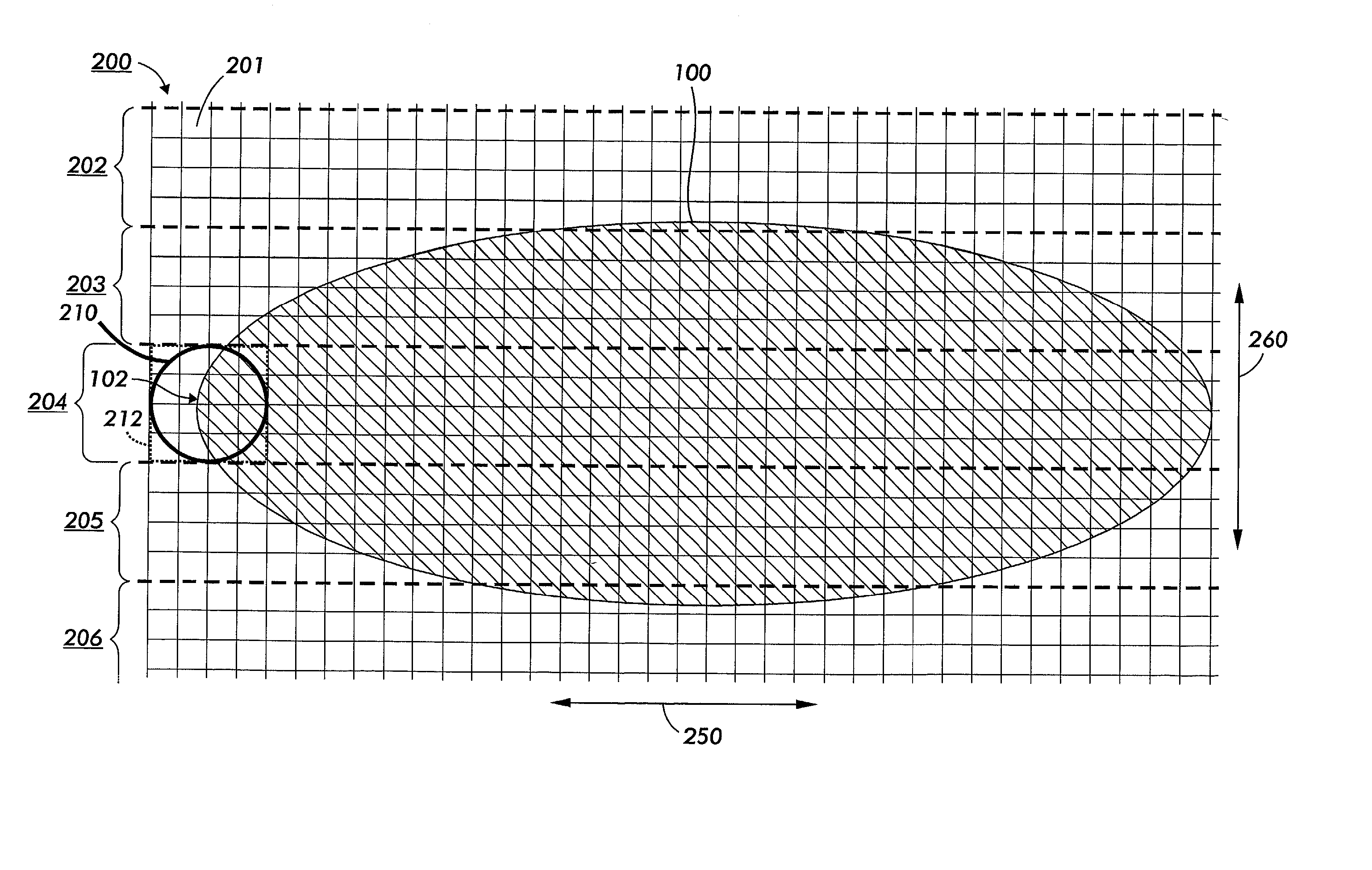
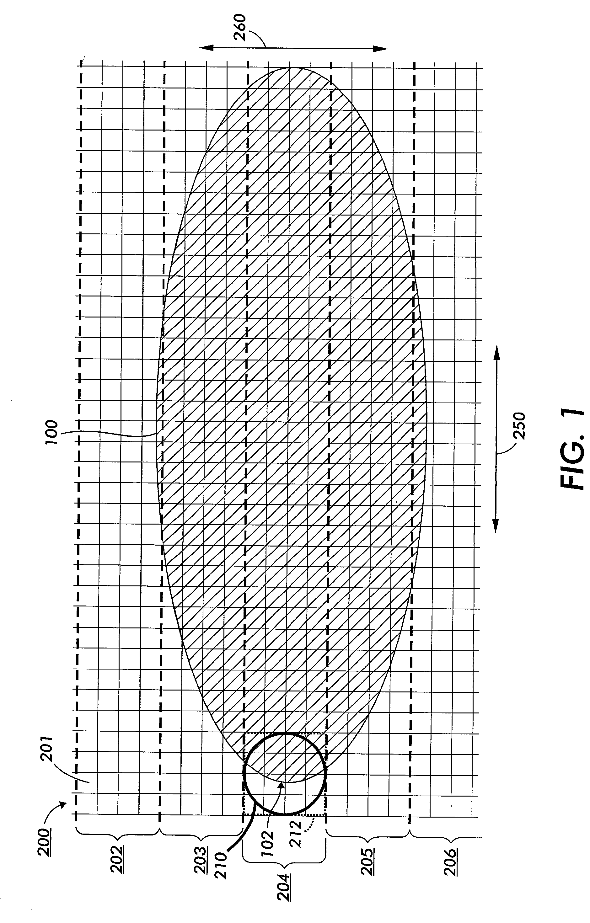
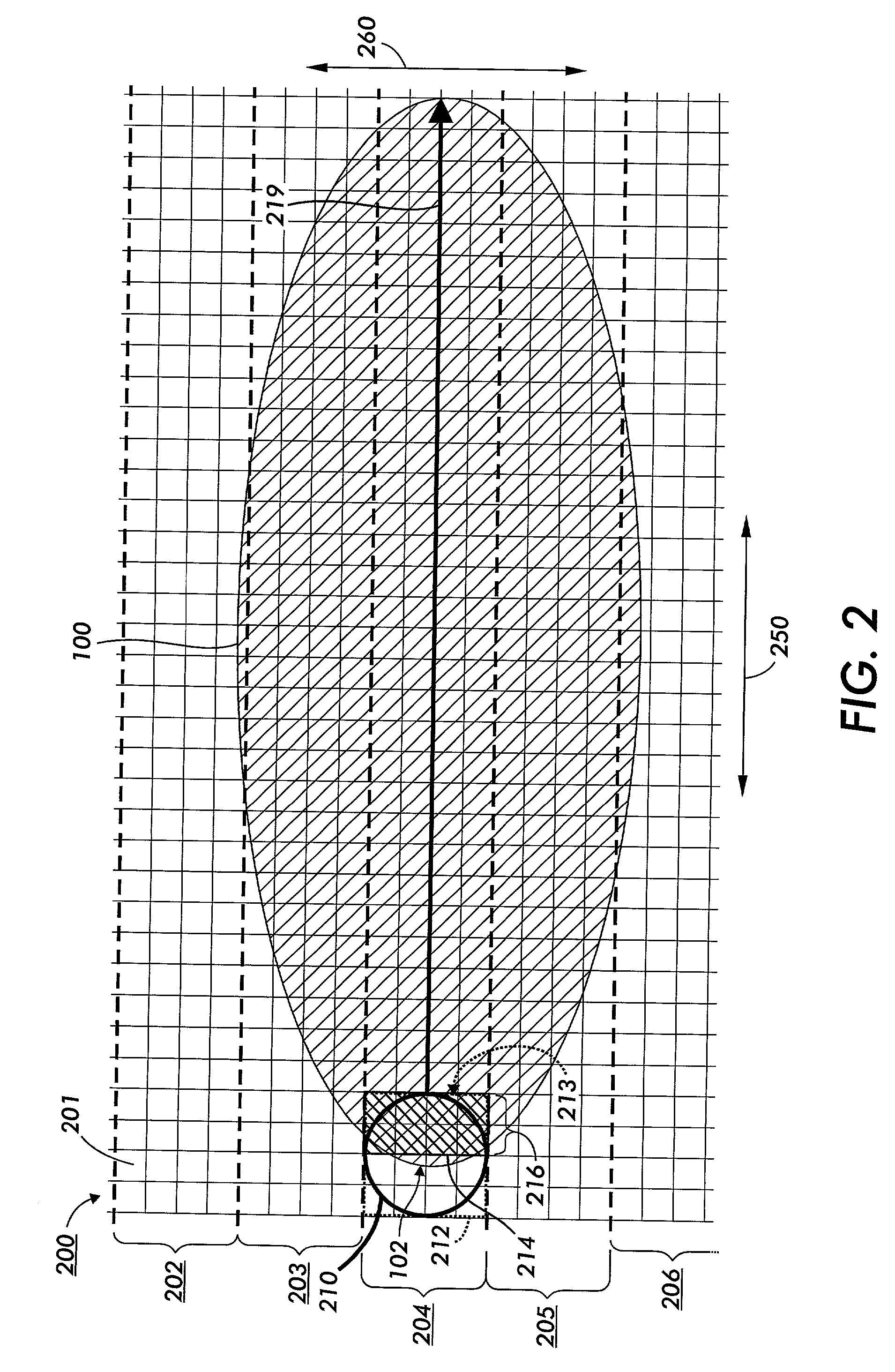
[0023] In various exemplary embodiments of the systems and methods according to this invention, the result of a high resolution integration of an image structure, such as a halftone dot-shape function, is clustered. For fast scan edges of an image, i.e., those vertical edges of the image that extend across a high addressability direction, this is simple. In particular, those fast scan edges tend to be easily determined, as those fast scan edges cross over the edges, i.e., the "horizontal window edges", of a high addressability sample window that extend along the high addressability, i.e., fast scan, direction. In contrast, when the edge of the image structure, such as the halftone dot-shape, extends across an edge of the high addressability sample window that does not extend along a high addressability direction, i.e., a "vertical" window edge, the sample window is incrementally altered, and in particular, is usually extended, in the horizontal direction in one or both directions along the horizontal axis until the edge of the image structure, such as the halftone dot-shape, no longer crosses either vertical window edge of the altered sample window.

Problems solved by technology

However, such high-frequency structures along the edges of the image structure, such as the halftone dot, often, if not invariably, result in artifacts, such as moir patterns or noise, when the halftone dots are moved to accomplish electronic registration.
In particular, dithering the edges of the image structures, such as the halftone dots, to ensure the proper tone is reproduced generally renders it impossible to avoid such moir patterns and / or noise in the resulting image when electronic registration is used.

Method used


Image

  • Systems and methods for generating binary clustered, irrational halftone dots
  • Systems and methods for generating binary clustered, irrational halftone dots
  • Systems and methods for generating binary clustered, irrational halftone dots

Examples


Embodiment Construction

[0047] This invention is directed to systems and methods used to modify how a spatially-distributed stimulus is modified to cluster image elements produced according to a shape function so that the shape of the image element resulting from the modified spatial modulation has edges that are clustered together.

[0048] The following detailed description of the exemplary embodiments of this invention will be presented in view of a raster output scanner (ROS) image forming apparatus. However, it should be appreciated that the systems and methods of this invention, as described herein, can be applied to an image forming apparatus that uses any type of stimulus, including any type of projected radiation of any wavelength, a spatially-modulated magnetic field and / or magnetic flux, a spatially-modulated applied electric potential, spatially-modulated applied heat energy, a spatially modulated direct application of toner, ink or other material used to create an image, or any other known or lat...


PUM


Abstract

The result of integrating a halftone dot-shape can be clustered. When the edge of the halftone dot-shape extends across a "vertical" edge of a window, the window is altered until the edge of the halftone dot-shape no longer crosses either vertical edge of the altered window. The image density of the portion of the halftone dot-shape contained within the altered window is determined. The block of image density of the portion of the halftone dot shape contained within the altered window is aligned with the right edge, the left edge, split between the left and right edges, or clustered in the "center" of the altered window. An amount of the determined block that extends into the original sample window is determined. This amount extending into the original window determines the amount of image density to be generated in the final output image based on that sample location of the window.

Description

BACKGROUND OF INVENTION[0001] 1. Field of Invention[0002] This invention relates to systems and methods for generating binary irrational halftone dots based on a spatially modulated stimulus.[0003] 2. Description of Related Art[0004] When creating image regions using halftoning, binary clustered halftone dots are desirable. In particular, binary clustered halftone dots often produce the least amount of noise and the best highlights. Conventional halftoning adds a two-dimensional, spatially periodic, dot screen or line screen structure to the images to be halftoned. Typically, the same screen, or at least a number of essentially identical screens, are used to halftone each of the color image separation layers of a polychromatic, i.e., color, image. However, the halftone screens are oriented at different angles for printing the respective halftone color image separation layers.[0005] Digital halftoning has evolved as a method of rendering the illusion of continuous tone, or "contone",...

Claims


Application Information

Patent Timeline
Patent Type & Authority Applications(United States)
IPC IPC(8): B41J2/52G06T5/00H04N1/405
CPCH04N1/4055
Inventor CURRY, DOUGLAS N.
Owner XEROX CORP
Learn More