Transmission and reception of duobinary multilevel pulse-amplitude-modulated optical signals using finite-state machine-based encoder

a multi-level pulse-amplitude modulation and encoder technology, applied in the field of optical communication systems, can solve the problems of poor average optical power efficiency of multiple-subcarrier modulation, difficult to fabricate filters with sufficiently sharp cutoff and match optical carrier frequency and filter cutoff frequency with sufficient accuracy, and difficult to implement single-sideband optical modulation schemes proposed to da

Inactive Publication Date: 2003-01-16
OPNEXT SUBSYST
View PDF0 Cites 54 Cited by
  • Summary
  • Abstract
  • Description
  • Claims
  • Application Information

AI Technical Summary

Problems solved by technology

A few prior works have described single-sideband modulation of optical signals, but the single-sideband optical modulation schemes proposed to date are very difficult to implement in practice.
Optical vestigial-sideband amplitude modulation can be implemented by first generating an amplitude-modulated optical signal and then filtering it with an optical filter having a sharp cutoff centered at the optical carrier frequency but, in practice, it is difficult to fabricate filters having sufficiently sharp cutoff and to match the optical carrier frequency and filter cutoff frequency with sufficient accuracy.
Multiple-subcarrier modulation offers poor average optical-power efficiency (e.g., compared to on-off keying, which is the same as 2-ary pulse-amplitude modulation), and this efficiency decreases further as the number of subcarriers is increased.
Multiple-subcarrier modulation requires transmitters and receivers significantly more complicated than those required by baseband modulation techniques, such as on-off keying and M-ary pulse-amplitude modulation.
However, very complicated phase-sensitive detection techniques are required to recover the transmitted bits, such as synchronous homodyne or synchronous heter

Method used


Image

  • Transmission and reception of duobinary multilevel pulse-amplitude-modulated optical signals using finite-state machine-based encoder
  • Transmission and reception of duobinary multilevel pulse-amplitude-modulated optical signals using finite-state machine-based encoder
  • Transmission and reception of duobinary multilevel pulse-amplitude-modulated optical signals using finite-state machine-based encoder

Examples


embodiment 247

[0085] In the encoder 247, the 4-ary pulse-amplitude modulation symbol sequence D.sub.m, denoted by 231a, is input to a finite-state machine, denoted by 232b. The blocks of 2 information bits 250 and 251 are also input to 232b. Within 232b, 250 and 251 are input to a subsequence decomposer 237a, which is implemented using an AND gate with inverters on the inputs. The output of 237a is the logical subsequence S.sub.m,0, which is denoted by 238a. The logical subsequence 238a is input to a logical subsequence precoder, which is denoted by 239. The precoder 239 includes the exclusive-OR gate (modulo-2 subtractor), denoted by 240, as well as the one-symbol delay, denoted by 241, interconnected in a feedback arrangement. The output of the logical subsequence precoder 239 is a logical precoded subsequence Z.sub.m, denoted by 242a. The logical precoded subsequence 242a is related to the logical subsequence 238a by the rule that, during the mth symbol interval, Z.sub.m=S.sub.m,0-Z.sub.m--1 (...

embodiment 371

[0121] The logical subsequence 238a is input to a logical subsequence precoder, which is denoted by 239. The precoder 239 includes the exclusive-OR gate (modulo-2 subtractor), denoted by 240, as well as the one-symbol delay, denoted by 241, interconnected in a feedback arrangement. The output of the logical subsequence precoder 239 is the logical precoded subsequence Z.sub.m, denoted by 242a. The logical precoded subsequence 242a is related to the logical subsequence 238a by the rule that, during the mth symbol interval, Z.sub.m=S.sub.m,0-Z.sub.m--1 (mod2), where Z.sub.m-1 (243a) is the value of the logical precoded subsequence Z.sub.m (242a) during the previous symbol interval, m-1. We note that the precoder 239 is itself a finite-state machine with input S.sub.m,0 (238a), output Z.sub.m (242a), and two states, corresponding to the two possible values of Z.sub.m-l (243a). The operation of 239 is described by the state-transition diagram 234, shown in FIG. 3b. In 234, we have labele...


PUM


Abstract

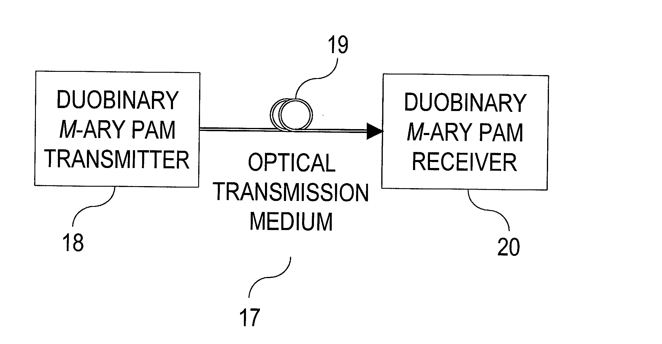
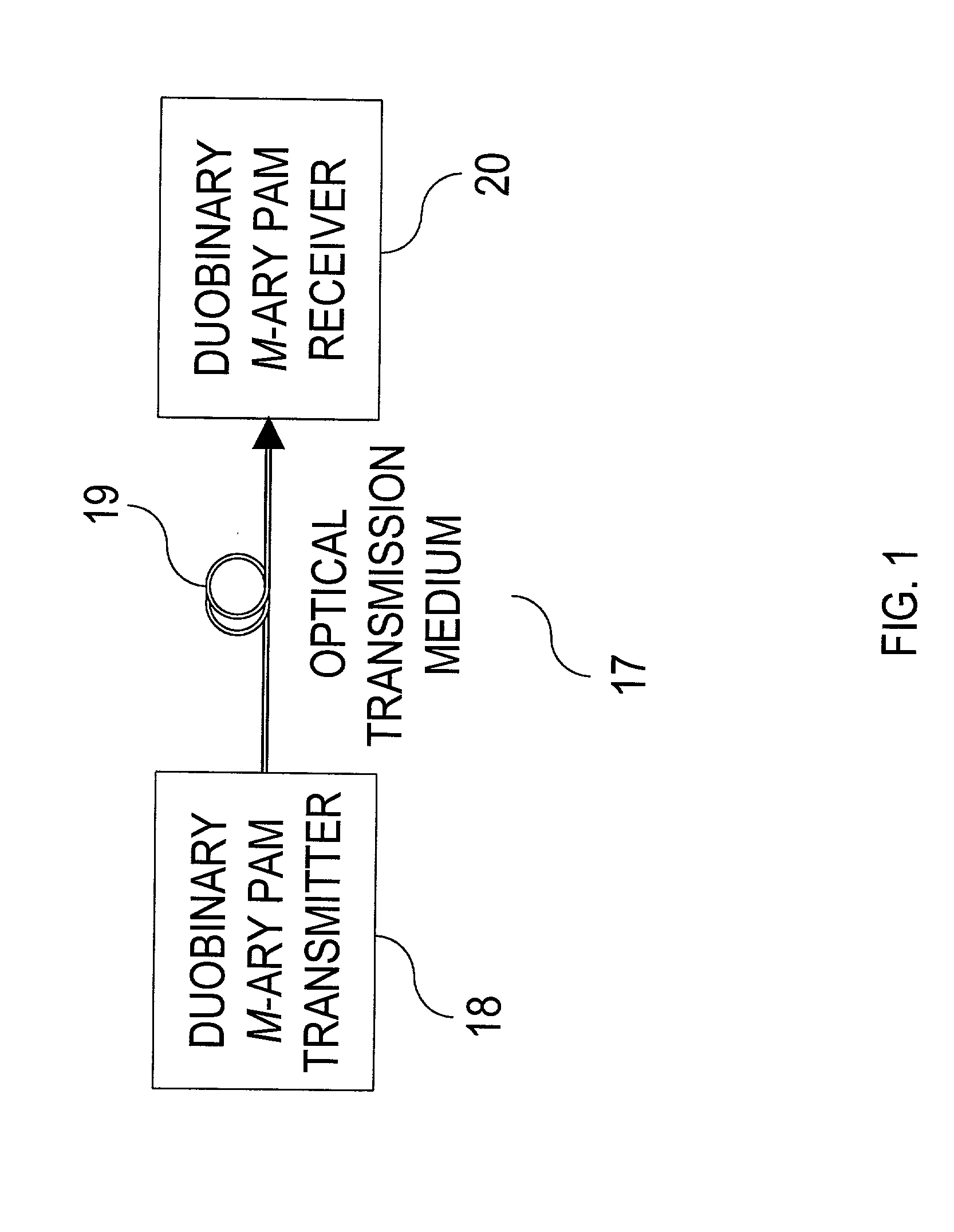
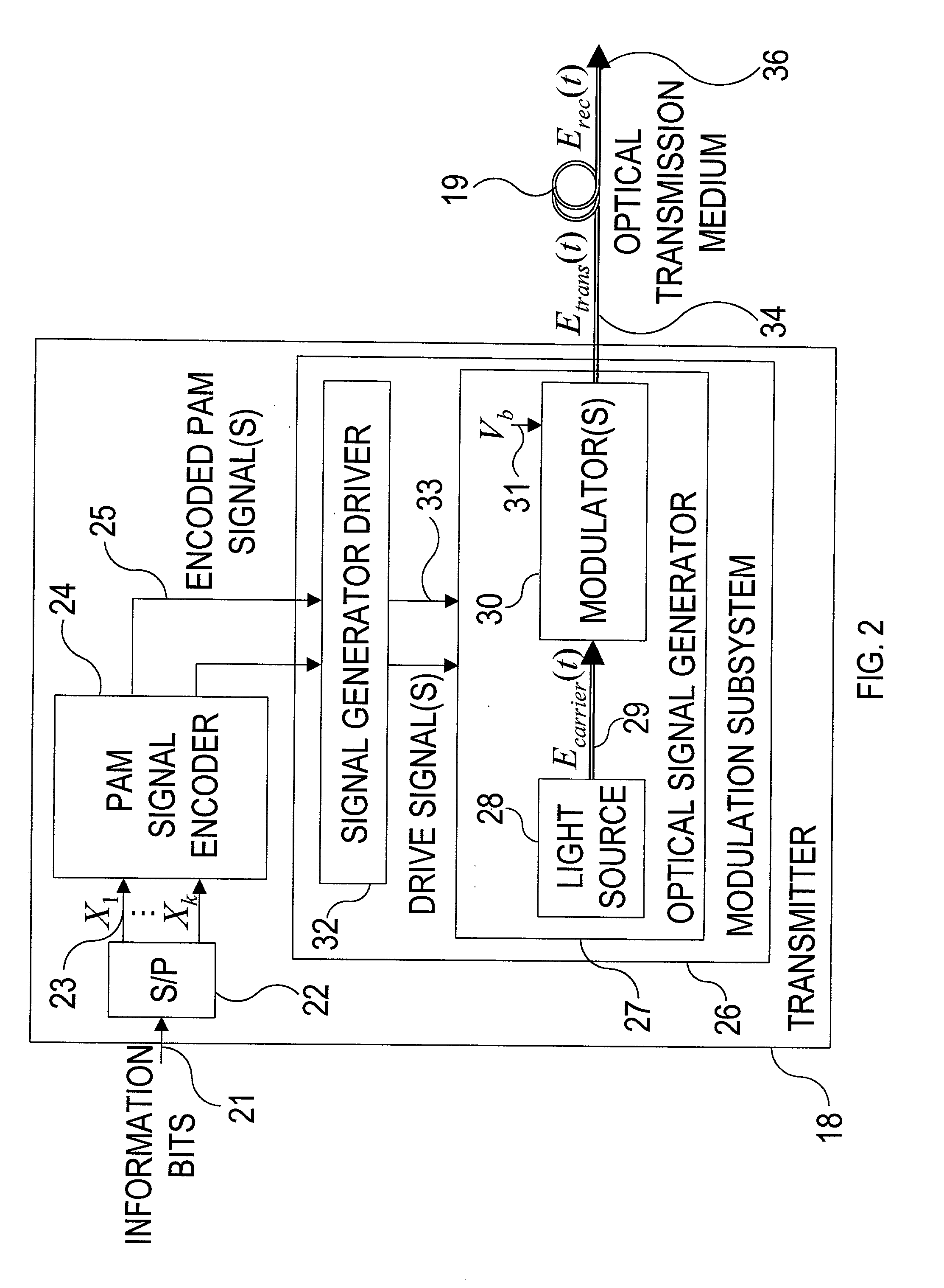
Methods and apparatus to transmit and receive information bits encoded in duobinary, multilevel pulse-amplitude-modulated (PAM) optical signals are described. The transmitted optical signal has a narrow optical spectrum and a low symbol rate. Information bits are encoded in a M-ary PAM symbol sequence, where M>=2. The PAM symbol sequence is input to a finite-state machine, which yields an encoded sequence that changes sign between two symbol intervals when the encoded sequence takes on a nominally zero value during an odd number of intervening symbol intervals. The encoded sequence is lowpass filtered and modulated onto an optical electric field. The receiver processes a received optical electric field to obtain an electrical signal proportional to the received optical intensity, and performs M-ary symbol-by-symbol decisions to recover the transmitted information bits, without potential error propagation.

Description

[0001] This application is a continuation of pending application Ser. No. 09 / 774,288 filed Jan. 29, 2001 by the same inventors and assigned to the same assignee.[0002] 1. Field of the Invention[0003] The invention relates generally to optical communication systems and, more particularly, to transmission and reception of digital information bits encoded in duobinary, multilevel pulse-amplitude modulation optical signals which, for a given bit rate, have a narrow optical spectrum and low symbol rate, and enable the information bits to be recovered from the intensity of the received optical signal without potential error propagation.[0004] 2. Description of the Prior Art[0005] It is well known that in optical communication systems conveying digital information, whether they transmit a single signal at a single carrier wavelength or transmit multiple signals at different carrier wavelengths (i.e., employ wavelength-division multiplexing), for a fixed bit rate per carrier wavelength, it ...

Claims


Application Information

Patent Timeline
IPC IPC(8): H04B10/12H04B10/148H04B10/155H04B10/158H04L25/49
CPCH04B10/5161H04B10/5167H04B10/524H04B10/60H04B10/63H04B10/64H04L25/4917
Inventor KAHN, JOSEPH MARDELLHO, KEANGPO
Owner OPNEXT SUBSYST
Why Eureka
Try Eureka