Artillery firing system

a firing system and artillery technology, applied in the direction of firing/trigger mechanisms, weapons, weapon components, etc., can solve the problems of heavy structural reinforcement/modification of the mounting platform, vehicle, still very large, and requires a heavy structure to withstand, so as to increase the efficiency of the cradle and the traversing mechanism, and achieve the effect of reducing the backlash and simplifying the design

Inactive Publication Date: 2003-02-06
SINGAPORE TECH KINETICS
View PDF0 Cites 3 Cited by
  • Summary
  • Abstract
  • Description
  • Claims
  • Application Information

AI Technical Summary

Benefits of technology

[0022] Further, another objective is to simplify the design and increasing the efficiency of the cradle and traversing mechanism for the artillery firing system. We have found that, if the recoil cylinder is anchored directly to the saddle, the cradle becomes lighter when the recoil force bypasses the cradle. The external surface of the recoil cylinder is used as a sliding and guiding surface to allow the recoiling mass to slide during recoil when firing the gun. Furthermore, in a traversing mechanism, a steel cable is used in place of gears so that there is zero backlash.
[0023] Another objective of the invention is to improve the safety of the crew by reducing the blast (overpressure) at the gun crew area.

Problems solved by technology

Therefore, to set up the mortar system for firing will take at least a few minutes.
This will result in heavy structural reinforcement / modification of the mounting platform (vehicle).
However, even with a 60% reduction (60,000 kPa) of the firing force, it is still very large and requires a heavy structure to withstand it.
The following problems have been borne in mind when solving the deficiencies, such as lack of recoil buffering and accuracy of the mortar systems of the prior art, and the lack of manoeuverability of the whole vehicle.
Thus the recoil mechanism has never been considered for use in the mortar system.
However, when the mortar system is platform-mounted (vehicle-mounted), the recoil forces become more critical compared to the weight of the individual sub-assembly.
Hence, some system integrators have incorporated the recoil mechanism to absorb the high recoil force, but this mechanism may not be efficient as the recoiling mass is too low to absorb the firing energy effectively and subsequently convert it to the recoil braking force.
The big and long cylindrical sliding surface on the barrel carries an excessive amount of weight.
On the other hand, there are minimum number of parts attached on the recoiling mass, which reduces the effectiveness of the buffering of the recoil.
However, the cradle is complex in both design and manufacturing.
The cradle is, however, complex in both design and manufacturing.
Its weight is very critical.
Therefore, the muzzle brake has never been considered for the mortar system.
The bomb will be unstable because of gas turbulence at the muzzle.
Trying to re-stabilize the flight path of the bomb during flight will result in the bomb losing its kinetic energy and accuracy.
The acceptable backlash in the traversing mechanism for accurate gun laying demand high precision and costly components.
Another disadvantage is that the gear teeth have friction due to their relative movements and are prone to wear and tear since it is very difficult to protect against dust and dirt in its operating environment.
The uneven wear and tear will cause malfunction of the anti-backlash mechanism after prolonged usage.
Furthermore, it has a non-linear (cosine error) correlation movement between the linear actuator and the rotating action.
This will complicate the control system for a closed-loop power drive system.

Method used


Image

  • Artillery firing system
  • Artillery firing system
  • Artillery firing system

Examples


Embodiment Construction

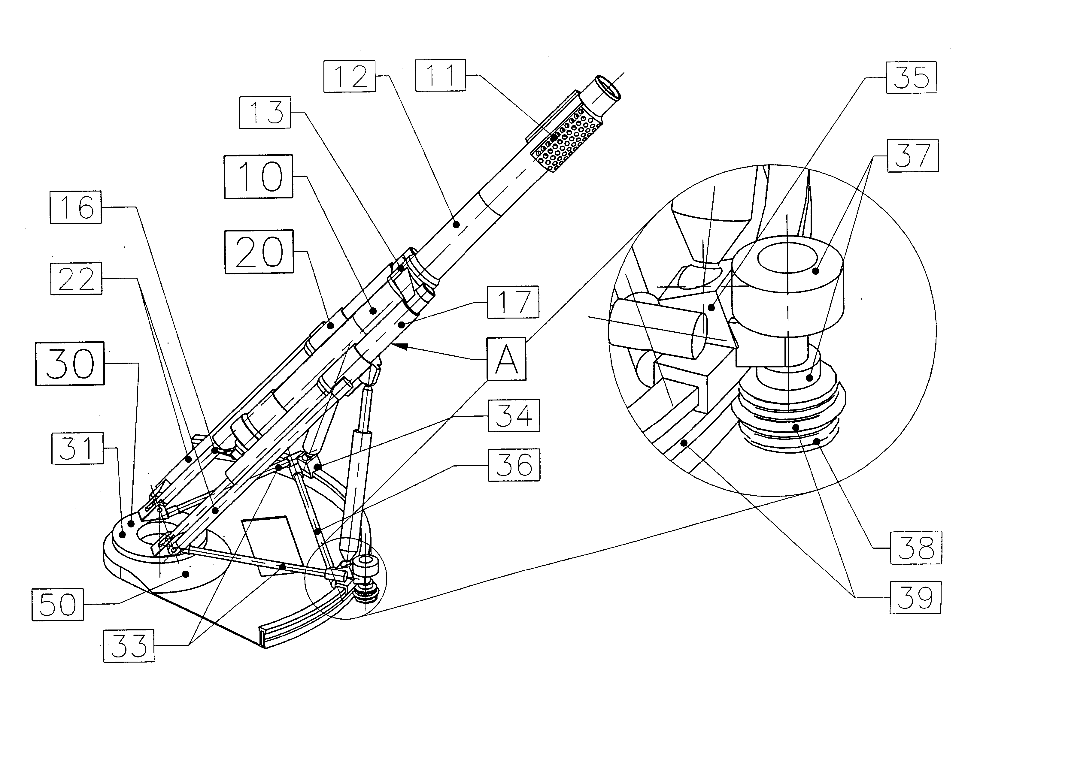
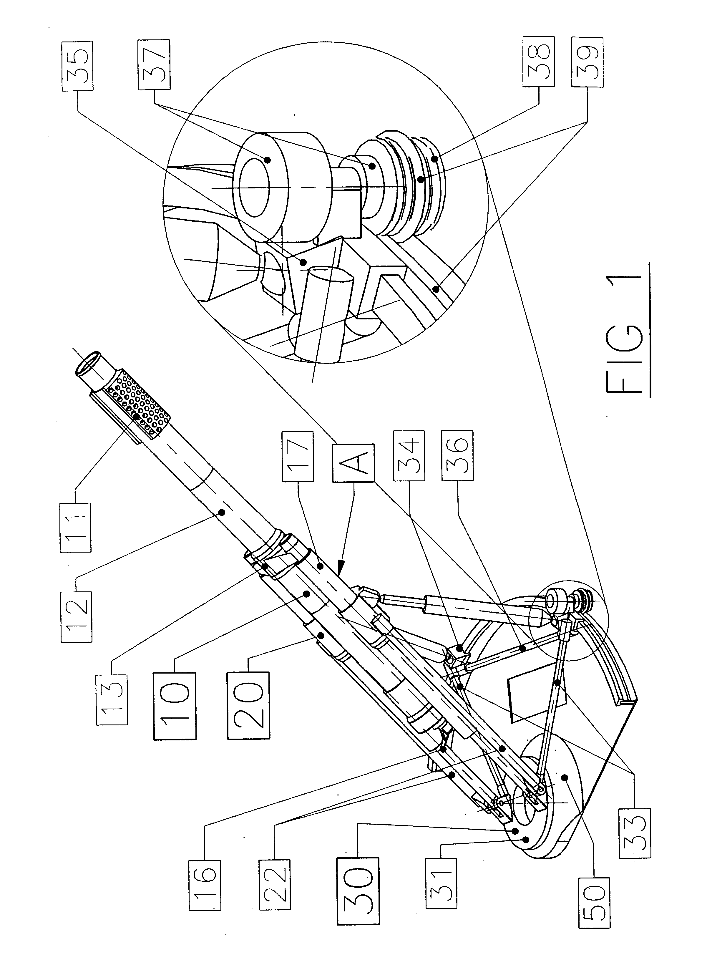
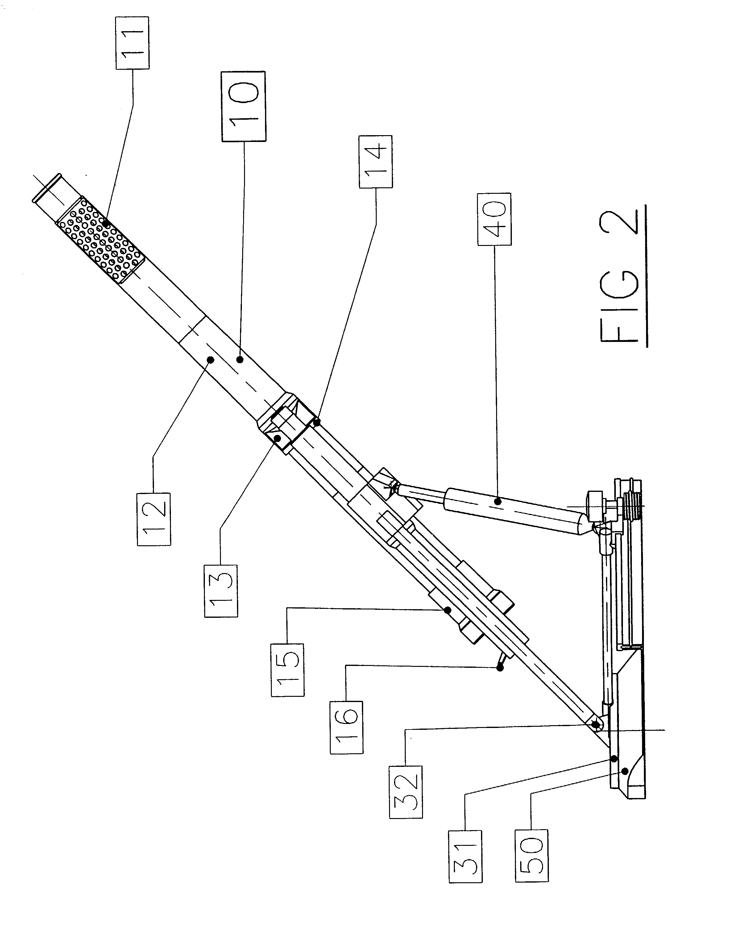
[0058] FIG. 1 is an isometric view of the mortar system according to the preferred embodiment of this invention. FIG. 1 should be read with FIGS. 2, 3 and 4 which illustrate the side, plan and front views of the mortar system respectively. The mortar system consists of the recoiling mass 10, elevating mass 20, traversing mass 30 and track assembly 50.

[0059] Recoiling mass

[0060] The recoiling mass 10 consists of a muzzle brake 11, barrel 12, breech 15, yoke 13, recoil buffer cylinder 17 and lock nuts.

[0061] A muzzle brake 11 with a pepper-port design is located at the front end of the barrel. It could either be integrated into the barrel 12 (mono-block) or detachable for ease of production. The breech 15 with the firing mechanism (not shown) and firing lever 16 are attached at the other end of the barrel to form the chamber for firing. The barrel 12 is supported by the yoke 13 and is secured by the lock-nut yoke 14.

[0062] The two recoil buffer cylinders 17 are attached to the yoke 13...


PUM


Abstract

A recoil buffering apparatus for use with an artillery gun of the type comprising a breech assembly (15) connected to a barrel (12), the breech assembly (15) having a firing mechanism for firing a projectile through an open end of the barrel (12). The recoil buffering apparatus comprises a recoil buffering means adapted to be fixed to the barrel (12) and movable therewith during recoil action of the barrel (12) caused by firing of the projectile, and a support means associated with the recoil buffering means for supporting the recoil buffering means and thereby supporting the barrel (12) and breech assembly (15) through the recoil buffering means. An elevating apparatus and a traversing apparatus for an artillery gun are also described. The artillery gun can also be provided with a muzzle brake (11).

Description

[0001] This invention relates to a platform or vehicle-mounted artillery firing system and in particular to a platform or vehicle-mounted mortar system and improvements in relation thereto.BACKGROUND AND PRIOR ART[0002] Traditionally, a mortar system was an infantry and commando weapon that was designed for man-packing. It had to be broken down into a few sub-assemblies to resolve the weight constraint necessitated by man-packing. Therefore, to set up the mortar system for firing will take at least a few minutes. However, mortar systems have now been mounted on various vehicles to meet the quick response required in performing hit-and-run missions demanded in modern warfare.[0003] The traditional mortar system consists of a barrel and breech assembly, bipod assembly and a base-plate. The breech piece has a spherical joint with the base-plate sitting on the ground. The bipod assembly is used for supporting the barrel and for fine adjustment of its elevation and travel. The gas pressu...

Claims


Application Information

Patent Timeline
Patent Type & Authority Applications(United States)
IPC IPC(8): F41A25/20
CPCF41A25/20
Inventor ANG, TEOH HWA
Owner SINGAPORE TECH KINETICS
Why Eureka
Try Eureka