System, combination and method for controlling airflow in convective treatment

a technology of convective treatment and airflow, which is applied in lighting and heating apparatus, ventilation systems, heating types, etc., can solve the problems of tissue damage, fluid temperature at the distal end of the duct system may be affected, and heat loss from the convective treatment system

Inactive Publication Date: 2003-02-20
GEN ELECTRIC CAPITAL +1
View PDF7 Cites 145 Cited by
  • Summary
  • Abstract
  • Description
  • Claims
  • Application Information

AI Technical Summary

Benefits of technology

0017] It is an object of this invention to automatically correct the condition where an air supply duct that is still conducting pressurized air is not connected to a convective device.

Problems solved by technology

Heat is lost from a convective treatment system whenever a temperature gradient exists between it and the ambient environment.
During normal operation of the system, the temperature of the air expelled onto the person is maintained at a level that is generally higher than the person's skin surface temperature, but not high enough to cause tissue damage.
If any factors upon which the assumption of predictability depends are altered, however, the fluid temperature at the distal end of the duct system may be affected.
One hazard associated with the use of convective treatment is burns.
First-, second-, and third-degree bums have occurred through the improper use of convective treatment systems.
The bum hazard is accentuated by the intentional or accidental alteration of the intrinsic or extrinsic factors that moderate the heat loss in the system.
The alteration of any of these factors introduces an unpredictable amount of heat loss into the system, which can significantly alter the temperature or velocity of the heated air delivered to the person.
Either intentionally or accidentally, some users fail to connect the convective device to the distal end of the duct and allow the heated air discharged from the distal end to make direct contact with the person.
In other cases, operators have failed to connect the convective device to the duct and allowed the heated duct to make direct contact with the person's skin.
Despite warnings, training, and labeling, however, persons continue to be injured through misuse of warning devices.
Hosing causes at least four uniquely hazardous conditions to exist: 1) The loss of the resistance from the lack of an convective device leads to a decrease in the residence time of warmed air in the air supply duct.
As the warmed air has less time to cool in the air supply duct, it arrives at the distal end of the duct at a higher than normal temperature; 2) The lack of airflow resistance from the absence of the convective device also leads to an increase in the air velocity that is exhausted from the supply duct; The relative increase in air velocity can lead to significantly higher heat transfer rates if the air strikes the skin; 3) The lack of an convective device makes it possible for the high temperature and high velocity air to strike directly the person's skin over a very small area.
Nevertheless, it is the case that large caseloads and near-crisis conditions can distract the attention of those who are in charge of the immediate operation of convective treatment systems.
In such circumstances, the practitioner may be unaware of the development of conditions that pose a hazard of bums, or may be forgetful of known conditions that require close and constant attention.
However, these provisions must be implemented in the structure and operation of a blower, and implicate redesign and reconstruction of exiting blower architecture.

Method used


Image

  • System, combination and method for controlling airflow in convective treatment
  • System, combination and method for controlling airflow in convective treatment
  • System, combination and method for controlling airflow in convective treatment

Examples


embodiment 400

[0049] Refer now to FIGS. 4A and 4B for an understanding of another embodiment of the interface device. In these figures, the interface device embodiment 400 includes a sleeve 418 of flexible material having an open end 422 that transitions to a shallow bowl-like collar and an end 424 that has a normally closed configuration in which opposing sections of the sleeve 418 at the end 424 abut without being permanently joined. The sleeve 418 is made of a durable flexible plastic such as polypropylene or polyethylene and has a remembered shape that maintains the end 424 in its normally closed configuration. Opposing longitudinal living hinges 415 and 417 connect two opposing segments 419 and 420 of the sleeve 418. Forces applied in opposition to the living hinges 415 and 417 near the end 424 (indicated by arrows 435) cause the end 424 to open and the sleeve 418 to assume an open tubular configuration. When the opposing forces 435 are released, the sleeve 418 returns to its remembered shap...

embodiment 500

[0052] Refer now to FIGS. 5A-5C for an understanding of another embodiment of the interface device. In these figures, the interface device embodiment 500 includes a spring structure with a base ring 510 having an opening 511. An imaginary axis A, centered in and perpendicular to the base ring 510, may be defined. A pair of elongate flexible tines 512 and 514 are mounted in opposition on one surface of the base ring 510, extending along and beside the axis A. The other surface of the base ring 510 has the same shape and dimensions as the annulus 20a. The flexible tines 512 have the shapes of shallow descending arcs that open in opposite directions away from the axis A. The flexible tines 512 and 514 are formed from any appropriate flexible material that retains a memory of its original shape when flexed by an applied force and that returns to the remembered shape when the force is removed. One such material is a sturdy, durable plastic such as polypropylene or polyethylene. The flexi...

embodiment 600

[0054] Refer now to FIGS. 6A and 6B for an understanding of another embodiment of the interface device. In these figures, the interface device embodiment 600 includes a single frusto-conical section 610 made of a durable flexible material such as plastic and having a narrow end 628 and a wide end 630. Both of the ends 628 and 630 are open, and the wide end 630 transitions to a shallow bowl-like collar. At the narrow end 628 there are four elongate slots 612 that extend from the end 628 longitudinally along the section 610 for about a third of the length of the section 610. The slots are arrayed at 90.degree. around the narrow end 628 of the section 610 and define four corresponding legs 614 extending from the narrow end 628. The legs 614 are flexible and can be flexed inwardly toward one another. A ball or sphere 620 of light durable material such as plastic is disposed on the inside of the section 610, wherein it is free to move between the narrow end 628 and the wide end 630. The ...


PUM


Abstract

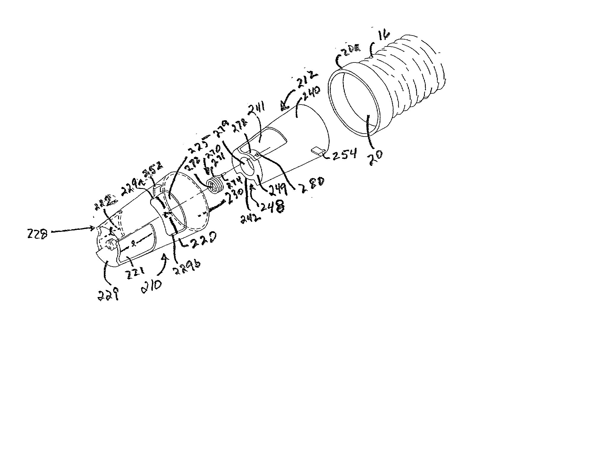
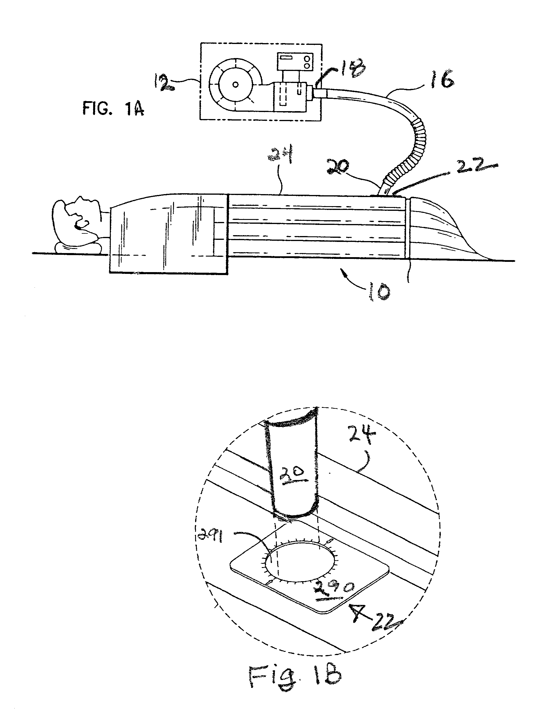
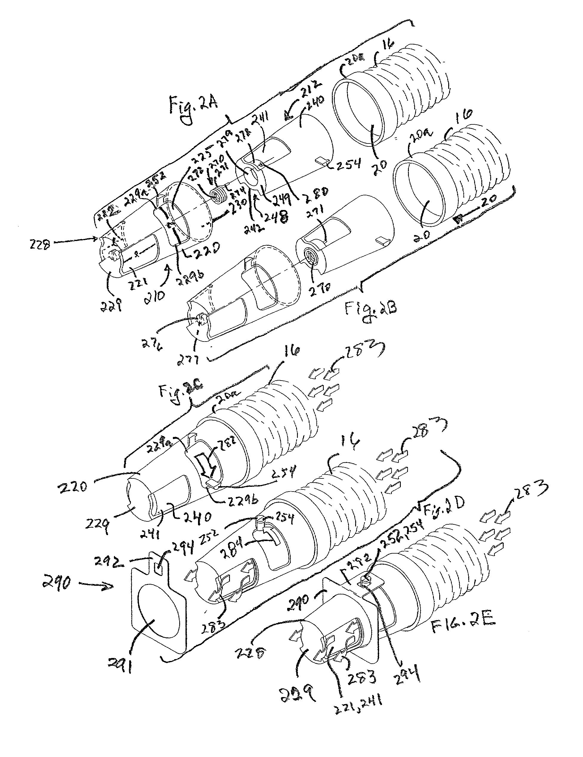
In a convective system that includes a blower to thermally treat and pressurize air, a convective device to receive and convect the thermally-treated pressurized air, and an air hose to conduct a flow of thermally-treated pressurized air from the blower to an inlet port in the convective device, an interface device is provided to control the flow of air at the interface where the inlet port and an end of the air hose operate to conduct the flow of air out of the air hose into the convective device. The interface device is received at the end of the air hose and operates to support the flow of air out of the end when the end and the inlet port are brought together. The interface device operates to stop, inhibit, or restrict the flow of air out of the end when the end and the inlet port are separated.

Description

PRIORITY AND RELATED APPLICATIONS[0001] Priority is claimed as a continuation-in-part of U.S. patent application Ser. No. 10 / 024,387, filed Dec. 17, 2001, which is incorporated herein by this reference.[0002] U.S. patent application Ser. No. 10 / 024,387 claims priority as a divisional of U.S. pattent application Ser. No. 09 / 546,078.[0003] This application contains subject matter related to the subject matter of U.S. patent application Ser. No. 09 / 138,774 filed Aug. 24, 1998, now U.S. Pat. No. 6,126,681, and to its continuation-in-part, U.S. patent application Ser. No. 09 / 546,078, filed Apr. 10, 2000. Both of these patent documents are incorporated herein by this reference.[0004] This invention relates generally to forced-air convection treatment of persons and, more particularly, to a system, a combination, and a method for controlling airflow in convective treatment in order to prevent injury to a person such as might occur when thermally-conditioned (heated or cooled) air is discha...

Claims


Application Information

Patent Timeline
Patent Type & Authority Applications(United States)
IPC IPC(8): A61F7/00
CPCA47C21/04A61F7/00A61F7/0097A61F2007/0055A61F2007/006A61H33/06A61H2033/061A61H2203/0456F24F7/065F24F2011/0004
Inventor DUREN, ALBERT PHILIP VANZIAIMEHR, ALLEN HAMIDROCK, JOHN PAULAUGUSTINE, SCOTT DOUGLASMAHARAJ, GARY RABINDRANATHARNOLD, RANDALL CHARLES
Owner GEN ELECTRIC CAPITAL
Why Eureka
Try Eureka