
Functional verification system

a verification system and functional technology, applied in the field of electronic design of integrated circuits, can solve the problems of inability to meet the requirements of design and fabrication

Inactive Publication Date: 2003-02-27
EVE
View PDF0 Cites 38 Cited by
  • Summary
  • Abstract
  • Description
  • Claims
  • Application Information

AI Technical Summary

Problems solved by technology

In addition, it may require several weeks of time to redesign and complete fabrication again.
Such levels of delays may be unacceptable, particularly in the high-technology markets where short design cycles are generally important.
For example, the scheduling of evaluation of a combinatorial block may be undesirably complicated as the inputs may need to be communicated from several CLOEs and due to the `hierarchy` in communication resulting from the central CLOE.
Accordingly, the embodiments of the co-pending application may not be suitable in some environments.
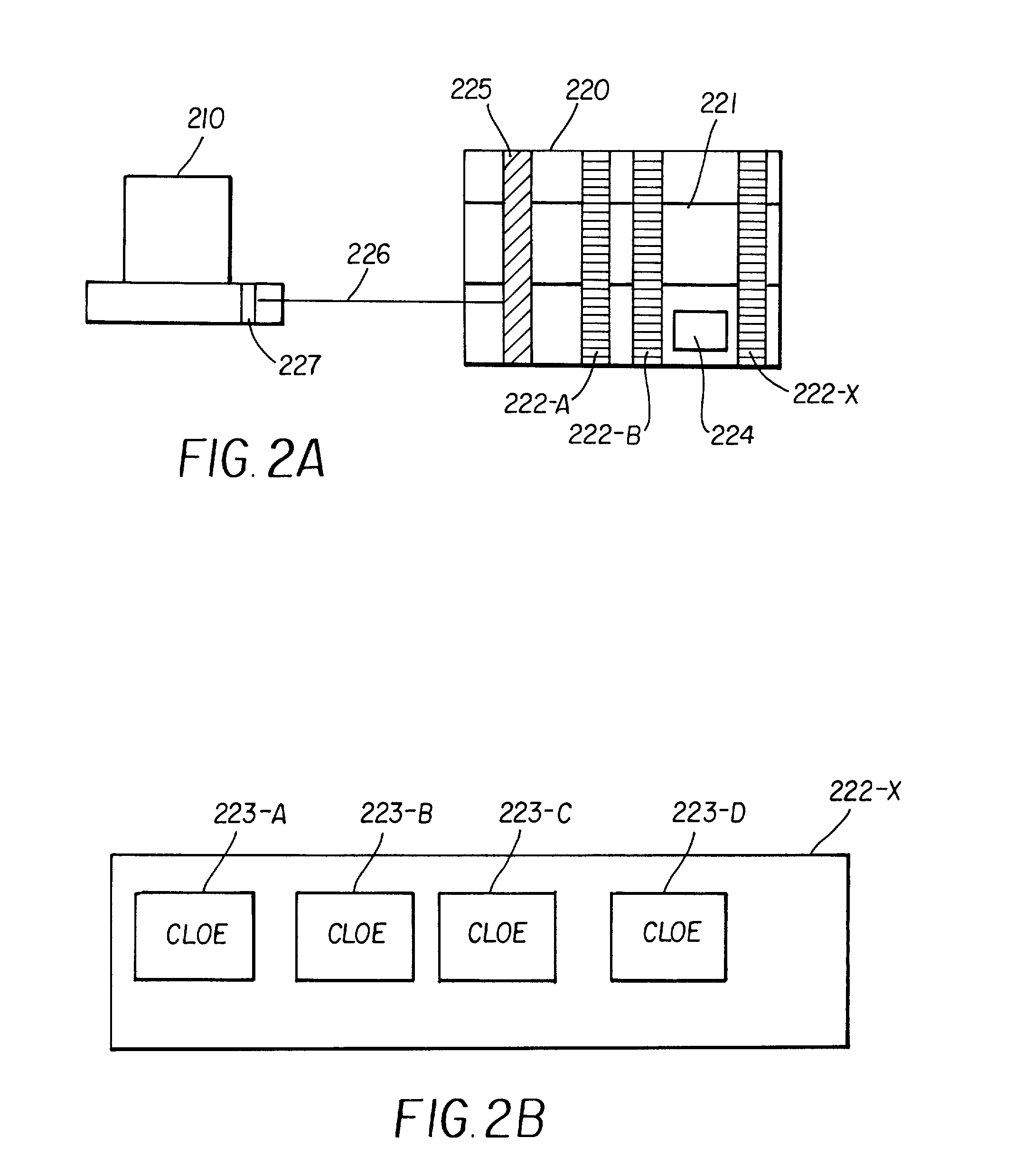
Sending the output data through RTC 225 and receiving the same data generally introduces pipeline delays, and the additional evaluations may need to be postponed.
The resulting delay in evaluations may be undesirable at least in some circumstances.
However, the sixteen CLOEs may be insufficient to perform functional verification of integrated circuit designs containing a large number of gates.
The presence of the loops poses special challenges in functional verification.

Method used


Image

  • Functional verification system
  • Functional verification system
  • Functional verification system

Examples


Embodiment Construction

[0236] The below pseudo code illustrates the manner in which loops may be evaluated until a desired condition (which can be a combination of many conditions) is attained. The code is described with reference to FIGS. 14 and 16 for further illustration.

[0237] Content of flow control memory 1473:

SET condition_bit N (P8)

RUN start_cond_block end_cond_block (P9)

IF condition_reg=0 JUMP label (P10)

RUN start_cycle_block end_cycle_block (P11)

label: (P12)

[0238] Content of cluster control memory 1472:

[0239] Set bit (8) of one of the clusters

within start_cond_block . . . end_cond_block (P13)

[0240] It should be first noted that the contents of flow control memory 1473 and cluster control memory 1472 are set based on the partitioning of the non-cycle based target design. In P8, a condition bit (specified as N) is set to 1 reflecting an initial condition (step 1630). In P9, a sequence of clusters, for example numbered 150 (start_cond_block) to 287 (end_cond_block), are evaluated. One of the cluste...


PUM


Abstract

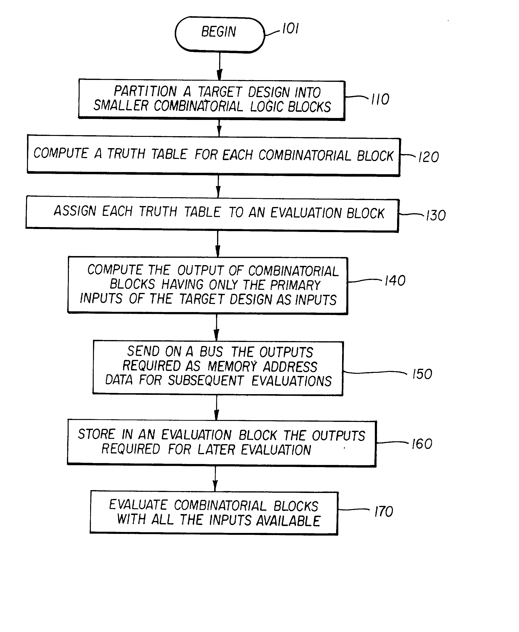
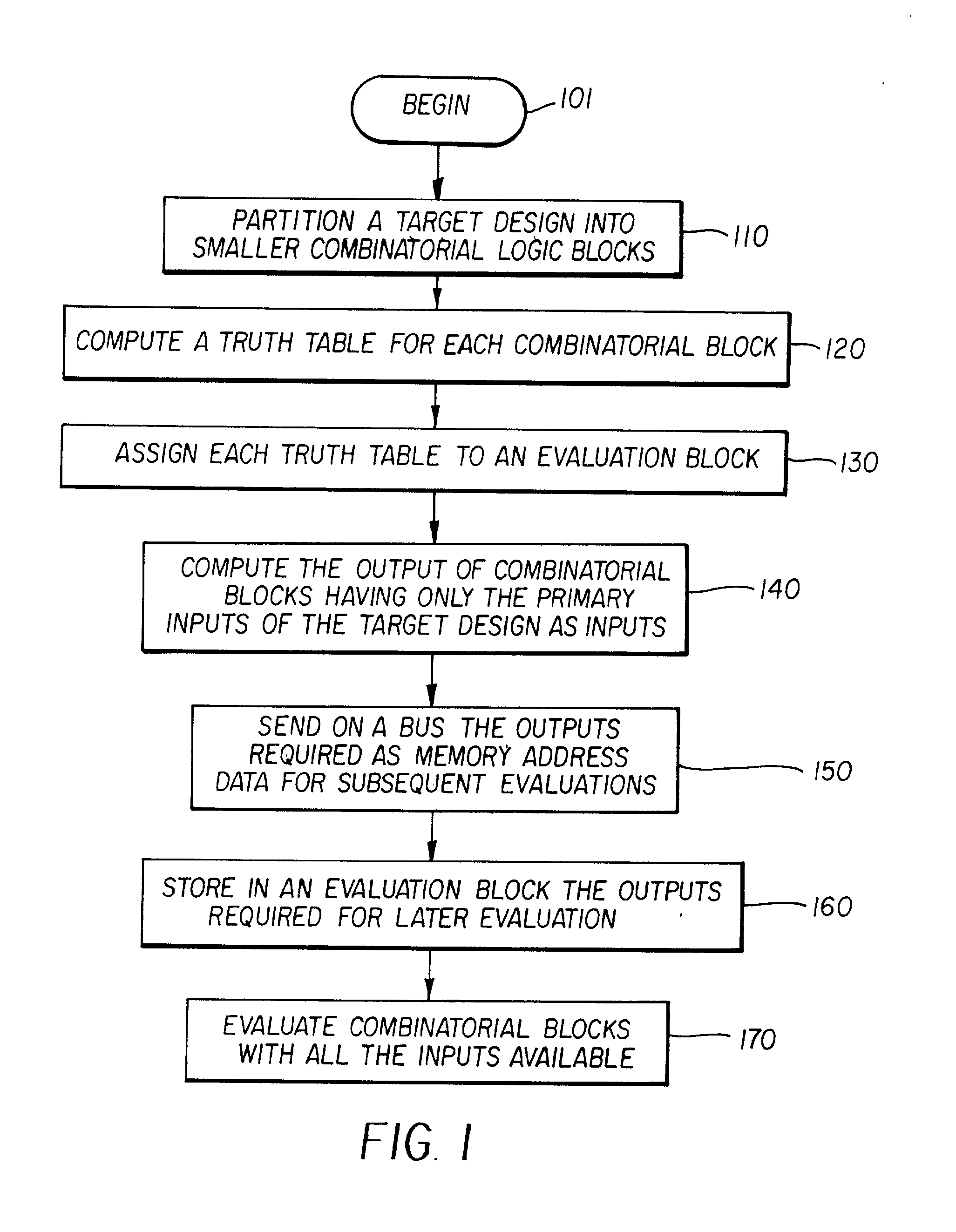
A functional verification system suited for verifying the function of non-cycle based integrated circuits (IC) design. The IC design is divided into a plurality of combinatorial blocks connecting sequential elements. Truth tables corresponding the divided blocks are computed and stored in a memory. The output values of the IC design are determined by evaluating the blocks. The evaluation typically entails one memory access as the truth tables are pre-computed and stored in a memory storage. Accordingly the output values are computed quickly. The storage is implemented using random access memories and a XCON is designed to ensure the dependencies are preserved during the evaluations.

Description

[0001] The present application is related to the following commonly assigned U.S. Patent Applications, which are all incorporated in their entirety into the present application herewith:[0002] (1) Application entitled, "Functional Verification of Integrated Circuit Designs", Serial Number: 09 / 097,874, Filed: Jun. 15, 1998, now U.S. patent number: 6,138,266, and is incorporated in its entirety herewith;[0003] (2) Co-pending application entitled, "Tracing the Change of State of a Signal in a Functional Verification System", Attorney Docket Number: THRS-0003, Serial Number; UNASSIGNED, Filed on even date herewith;[0004] (3) Co-pending application entitled, "Tracing Different States Reached by a Signal in a Functional Verification System", Attorney Docket Number: THRS-0005, Serial Number; UNASSIGNED, Filed on even date herewith;[0005] (4) Co-pending application entitled, "Run-Time Controller in a Functional Verification System", Attorney Docket Number: THRS-0006, Serial Number; UNASSIGN...

Claims


Application Information

Patent Timeline
IPC IPC(8): G06F17/50
CPCG06F17/5022G06F30/33
Inventor GANESAN, SUBBUBROUKHIS, LEONID ALEXANDERNARAYANASWAMY, RAMESHNIXON, IAN MICHAEL
Owner EVE
Learn More