Apparatus for generating a magnetic interface and applications of the same

a magnetic interface and apparatus technology, applied in the field of magnetic interfaces, can solve the problems of requiring expensive assembly techniques for the integration of discrete inductors onto the substrate, requiring less expensive printed inductors, and requiring a trade-off in circuit footprin

Inactive Publication Date: 2003-03-06
AVAGO TECH WIRELESS IP SINGAPORE PTE
View PDF4 Cites 29 Cited by
  • Summary
  • Abstract
  • Description
  • Claims
  • Application Information

AI Technical Summary

Problems solved by technology

The integration of discrete inductors onto a substrate requires expensive assembly techniques.
Therefore, RFICs that have discrete inductors are more costly to manufacture than those using printed inductors.
Unfortunately, replacing discrete inductors with less expensive printed inductors typically requires a tradeoff in circuit footprint.

Method used


Image

  • Apparatus for generating a magnetic interface and applications of the same
  • Apparatus for generating a magnetic interface and applications of the same
  • Apparatus for generating a magnetic interface and applications of the same

Examples


Embodiment Construction

[0047] 1. Properties of Electric and Magnetic Conductors

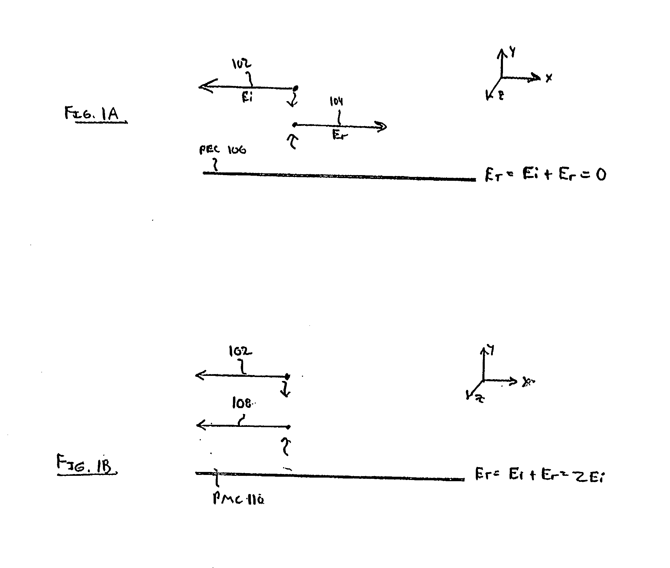
[0048] Before describing the invention in detail, it is useful to describe some properties of electric and magnetic conductors. FIG. 1A illustrates a perfect electric conductor (PEC) 106, and FIG. 1B illustrates a perfect magnetic conductor (PMC) 110. When an incident electric field (E.sub.1) 102 hits the PEC 106, a reflected electric field (E.sub.r) 104 is generated that is equal in amplitude and opposite in phase. Therefore, at the surface of PEC 106, the total electric field (E.sub.T) is 0, which is consistent with a short circuit. When the incident electric field (E.sub.1) 102 hits the PMC 110, a reflected electric field (E.sub.r) 108 field is generated that is equal in amplitude and also equal in-phase with the E.sub.1 102. Therefore, at the surface of the PMC 110, the total electric field is double that of the E.sub.1 102.

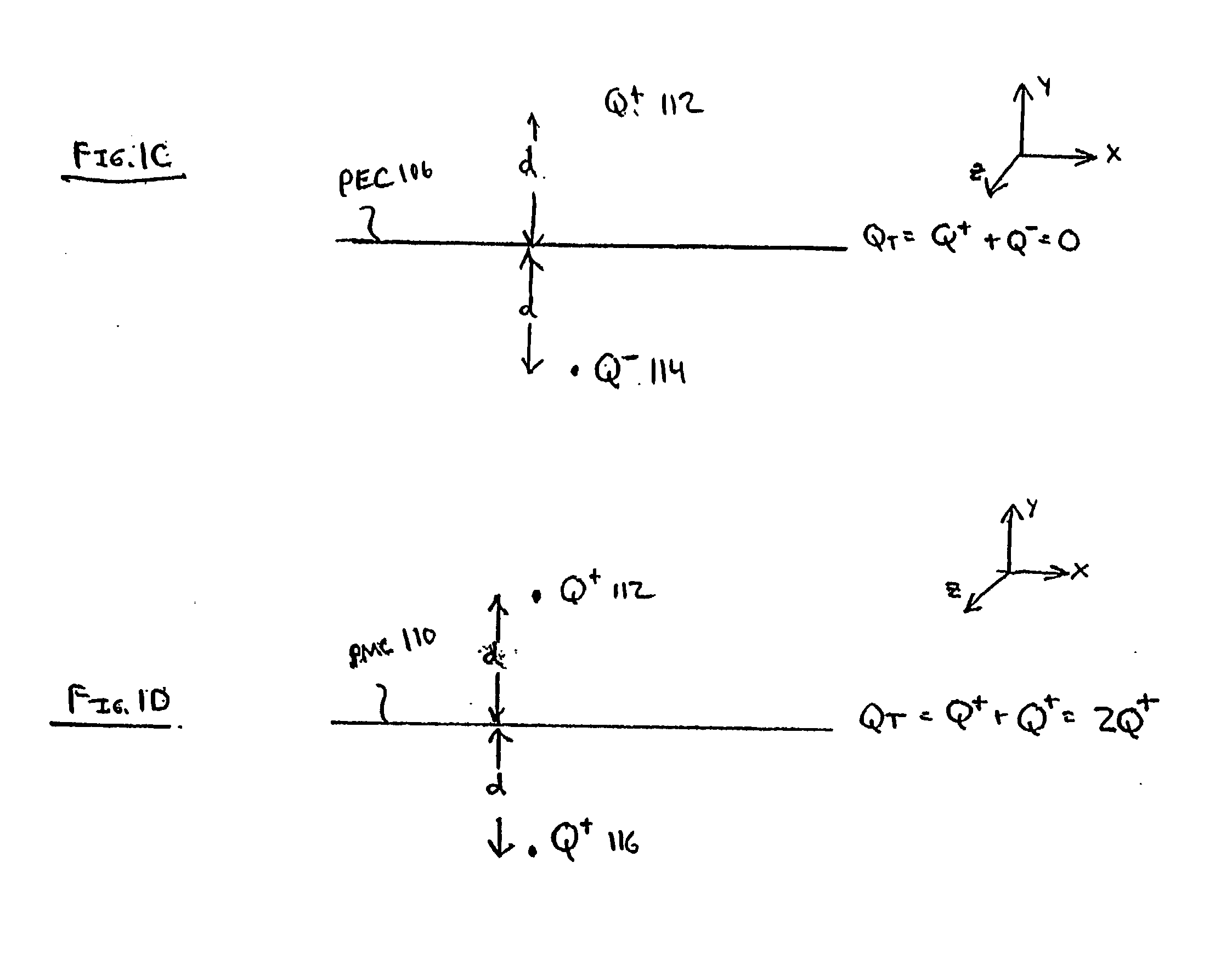
[0049] Referring to FIG. 1C, when a charge Q.sup.+ 112 is placed at a distance d above the PEC 106, t...


PUM


Abstract

A magnetic interface generator generates a magnetic interface at a center frequency f0. The magnetic interface generator is a passive array of spirals that are deposited on a substrate surface. The magnetic interface is generated in a plane at a distance Z above the surface of the substrate. The distance Z where the magnetic interface is created is determined by the cell size of the spiral array, where the cell size is based on the spiral arm length and the spacing S between the spirals. The center frequency of the magnetic interface is determined by the average track length DAV of the spirals in the spiral array. In embodiments, the spiral array is one sub-layer in a multi-layer substrate. The spacing S of the spiral array is chosen to project the magnetic interface to another layer in the multi-layer substrate so as to improve performance of a circuit in the plane of the magnetic interface. For example, the magnetic interface can be used to increase the inductance of a printed inductor circuit, and to increase the gain and match of a microstrip patch antenna. Furthermore, the magnetic interface reduces the traverse electric (TE) and transverse magnetic (TM) surface waves in the plane of the magnetic interface, which reduces unwanted coupling between transmission lines.

Description

[0001] This application claims the benefit of U.S. Provisional Application No. 60 / 314,166 filed on Aug. 23, 2001, which is incorporated herein by reference in its entirety.[0002] 1. Field of the Invention[0003] The present invention generally relates to a magnetic interface, and applications of the same.[0004] 2. Related Art[0005] Radio frequency and microwave integrated circuits (collectively called RFICs herein), include active components and passive components that are printed or deposited on a suitable substrate. The various active and passive components are connected together with transmission lines. Exemplary transmission lines include microstrip transmission line, stripline, and / or co-planar waveguide transmission line.[0006] Active components typically include one or more transistors that require DC bias for proper operation. Examples of active circuits include amplifiers, oscillators, etc. Passive components do not require DC bias for proper operation. Examples of passive c...

Claims


Application Information

Patent Timeline
IPC IPC(8): H01P3/08H01Q9/04H01Q9/27H01Q15/00H01Q21/06
CPCH01P1/2005H01P3/08H01Q9/0407H01Q9/27H01Q21/062H01Q15/0066H01Q15/002H01Q15/008
Inventor ALEXOPOULOS, NICOLAOS G.CONTOPANAGOS, HARRYKYRIAZIDOU, CHRYSSOULA
Owner AVAGO TECH WIRELESS IP SINGAPORE PTE
Why Eureka
Try Eureka