Nevertheless, problems are that, in the case of the vertical arrangement of the developing unit in the conventional two component developer material method, assembling of the apparatus to a compact body is limited and at the same time, it is inevitable that carrier attaches the photosensitive body and toner scatters owing to lowering of charge on the toner because supplying developer material from a developer stirring part to a developing member adjacent to the photosensitive body, i.e. a
reflux of developer material, becomes complicated.
Though one component method without carrier is proposed as another method, torque fluctuation of a rotational photosensitive body by contacting a developing roll to a photosensitive body results in color drift which is a drawback in a tandem method.
These result in image defects.
The strong
alternating current electric field disorders the toner layer on the electrostatic latent image bearing body (the photosensitive body) so that difficulty arises in color
pile up.
The
powder cloud developing method disclosed in the aforementioned Japanese laid-open patent publication JP1991-113474 has not been, however, paid general attention because a wire for the
auxiliary electrode is apt to get dirty and image deterioration occurs by vibration.
The apparatuses disclosed in Japanese laid-open patent publications JP1999-231652, JP1995-72733, JP 1995-92804, JP1995-128983, JP1984-121077 and JP2000-81788 have such drawbacks as prerequisites for a member for scraping toner or a
recovery roll, as a potential cause for deteriorating durability performance of toner owing to increasing stress of toner by applying special
recovery bias
voltage and as a loss of speed because of the necessary time for formation of a layer on the developing roll at the successive developing process.
These prior arts also have a cause of scatter of toner or
fogging owing to insufficient
electric charge by broadening a charge distribution of replenished toner or recovered supplied toner, as charge characteristic of toner on the developing roll varies to a large extent by deterioration of durability performance of toner when it is used for a long time.
Moreover, as it is troublesome to change deteriorated carrier, the arts have actually been of no practical use.
At the same time, the developing unit is constructed so that the toner roll, the magnetic roll and the stirring member are arrayed laterally, which results in difficulty in achieving a compact design.
Furthermore, in these conventional arts, the amount of toner in the toner layer on the developing roll varies when the second developing cycle is brought into operation after the first developing cycle together with a phenomenon which brings about a decline of image depth in the second developing cycle or the later cycle after a deep color developing owing to an insufficient amount of toner.
These means do not solve the aforementioned problems as the charge of the toner declines on account of an increase in the load on the developer material if the developing roll runs fast or if the machine is left idle for a considerable length of time.
These conventional arts have a drawback of a possible
hysteresis, which means the appearance of a ghost image as shown in FIG. 4(b), to overcome.
However, the apparatuses disclosed in Japanese laid-open patent publication JP1999-231652 and JP1996-128983 have a cause to deteriorate durability of toner owing to increasing stress to toner by a toner scraper or application of special bias for recovering toner.
These prior arts also have a cause of scatter of toner or
fogging owing to insufficient
electric charge by broadening a charge distribution of replenished toner or recovered supplied toner, as charge characteristic of toner on the developing roll varies to large extent by deterioration of durability performance of toner in case of using for a long time.
Moreover, it is troublesome to change deteriorated carrier so that the arts have actually been of no practical use.
The method has a drawback that a wire for the
electrode is apt to get dirty and has a possibility of image deterioration by vibration.
Contrary to that, a charge distribution of the toner in two component developer material becomes broad, even generating reversely charged toner for the toner on the developing roll having different charge mixes instantaneously with the toner in the magnetic
brush, which brings about disadvantages such as increasing scattering of toner from the magnetic brush or image defect.
It has such complicated construction that brushes for applying charge to electrodes are provided in two places where toner is flied to the donor roll from developing place and the magnetic roll.
This pushes up the manufacturing cost for the apparatus.
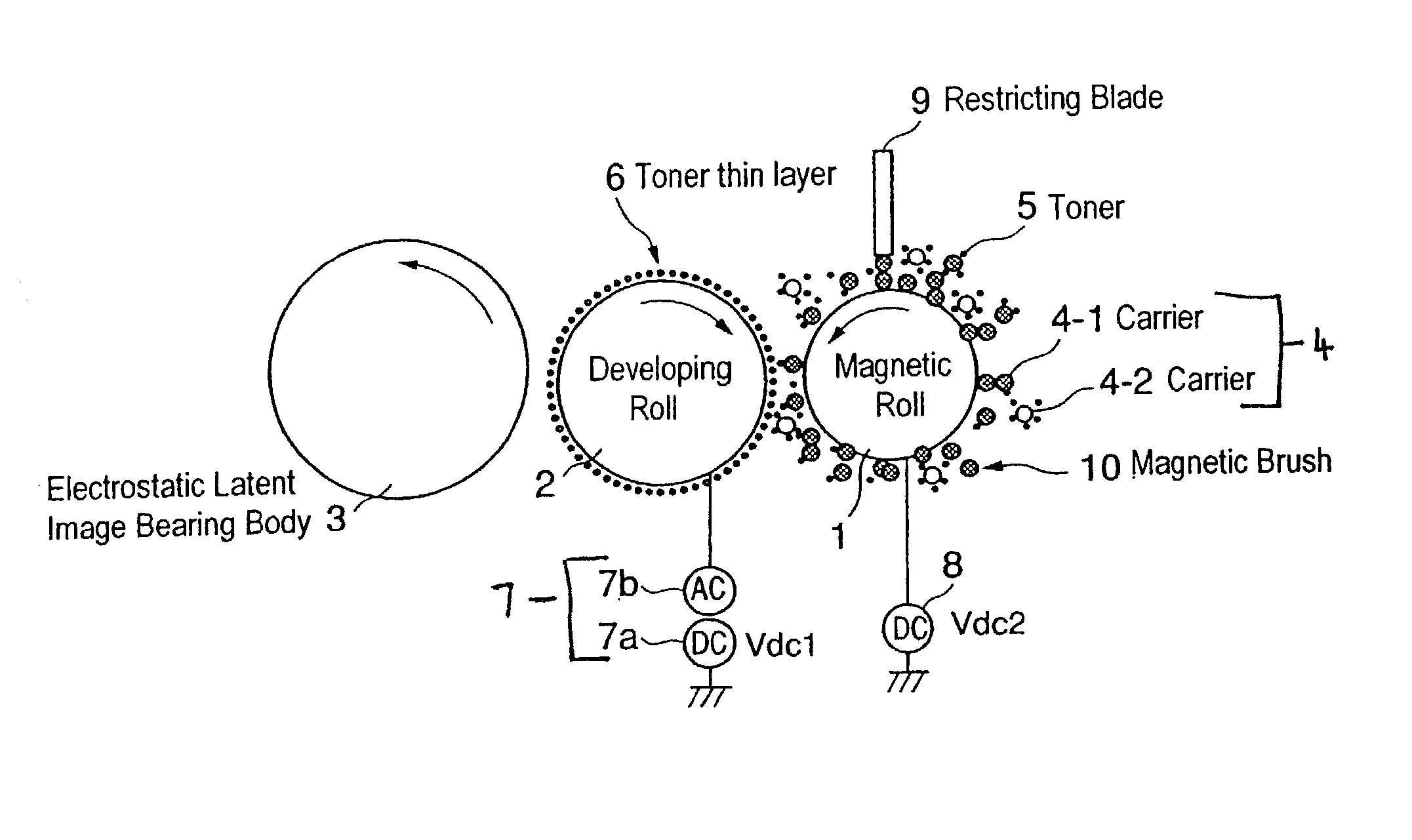
On the contrary, if a region for forming the magnetic brush in the axial direction on the magnetic roll is smaller than a region for forming a toner
thin layer in the axial direction on the surface of the developing roll, a uniform toner thin layer can not be prepared because the magnetic brush is disordered at both ends of the developing roll when forming an image.
If the
average diameter of the carrier particles is smaller than 3 times that of the toner particles, then it is difficult to recover toner because the attractive force to absorb is weak; if the
average diameter of the carrier particles is larger than 9 times that of the toner particles, then a longer time for recovering toner is necessary because the carrier particles have less occasions on which to contact toner particles.
Toner charge (hereinafter referred to as Q / M) increases to adhere tightly with electrostatic force to the surface of the carrier and an amount of toner consumption is estimated less than actual amount on account of a toner concentration (T / C) sensor's lowering of the out put value of permeability of the developer material, which results in malfunctioned supply of toner.
If the
ripple ratio of developer material is less than 5%, it is difficult to avoid a selective phenomenon.
If the
ripple ratio of developer material is more than 50% on the other hand, a prohibiting period of developer material replenishment is prolonged so that it becomes difficult to form a thin layer of developer material on the developer material bearing body.
When the saturated
magnetization of the low resistivity carrier declines to less than 67 mA m.sup.2 / g, sufficient effect cannot be achieved since both the
electrode effect at
recovery and the scraping effect by the magnetic brush decrease.
Generally, when 20% or more of the
surface coating of coated carrier has worn off, the ability to charge the toner properly is lost.
That is, when the
mixing ratio of toner is under 2% by weight, insufficient image depth is achievable on account of excessive electrical charge; when over 40% by weight, toner scatters from the developing device on account of insufficient electrical charge, which results in
contamination of the interior of the image forming apparatus or generation of toner fogging on the image.
Nevertheless, problem is the OPC is soft at the surface of the photosensitive layer so that the photosensitive layer is apt to be scraped by cleaning blade.
However, as a-Si photosensitive body is made to film by
glow discharge decomposition method, it is disadvantageous in view of economy due to a long
process time and a high production cost when the photosensitive layer is thick.
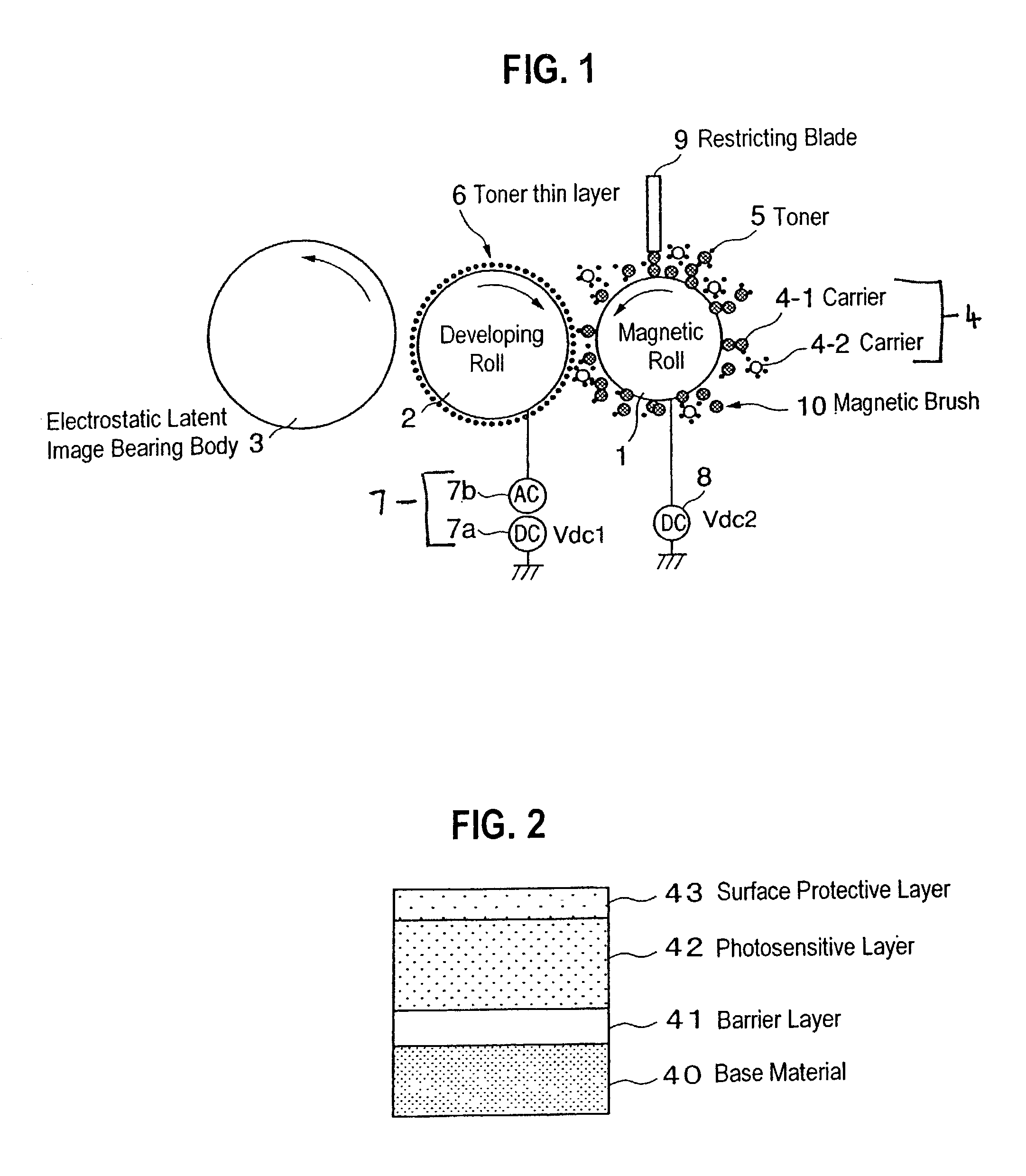
When the thickness of photosensitive layer 42 comes to under 10 micrometers, however, it becomes difficult to adjust the potential on the electrostatic latent image bearing body (photosensitive body) 3.
As a result, so called black points and fogging tends to appear easily.
Meanwhile, the thickness of the photosensitive layer exceeds 25 micrometers, it is difficult to exert low potential phenomenon so that
ozone generates easily, or a production time of the photosensitive layer is prolonged, which is disadvantageous in view of economy.
Furthermore, for the time over which a positive hole born in the charge generating layer of the photosensitive layer 42 moves to the surface of the photosensitive layer is prolonged, it becomes difficult to adjust the potential of electrostatic latent image bearing body (photosensitive body) 3, which results in the problem of generating fogging or decline of image depth.
Meanwhile, if the thickness of the surface protective layer 43 is more than 5 micrometers, it becomes a cause of image deterioration and is unprofitable because of a prolonged production time.
However, there is a case, where toner is not replenished since the toner concentration (T / C) is estimated higher than actual value because of low indicated value of permeability as the Q / M increases in
spite of continued consumption of toner by printing.

