Optical receiver including a dual gain path amplifier system

an amplifier system and optical receiver technology, applied in the field of optical receivers, can solve the problems of inability to provide the dynamic range needed to capture the output of an optical component over the entire sweep of the laser, the inability to test using a step-and-measure system, and the inability to complete measurement in hours

Active Publication Date: 2003-04-03
NEWPORT CORP
View PDF10 Cites 56 Cited by
  • Summary
  • Abstract
  • Description
  • Claims
  • Application Information

AI Technical Summary

Problems solved by technology

Since more data points may be measured in systems that have larger wavelength ranges and/or higher resolution, testing using a step-and-measure system may take a undesirable amount of time.
In a step-and-measure system, this measurement may take hours to complete.
However, in some receiver components (e.g., analog logarithmic amplifiers), there may be a tradeoff between speed and dynamic

Method used


Image

  • Optical receiver including a dual gain path amplifier system
  • Optical receiver including a dual gain path amplifier system
  • Optical receiver including a dual gain path amplifier system

Examples


Embodiment Construction

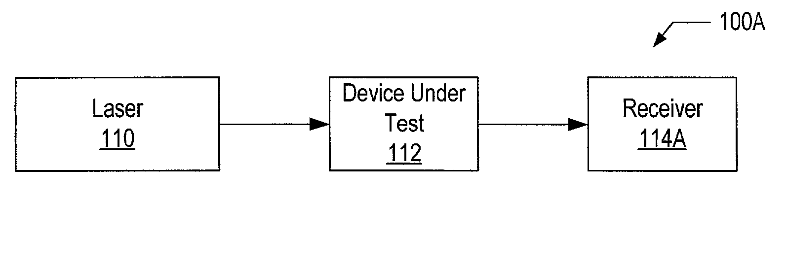
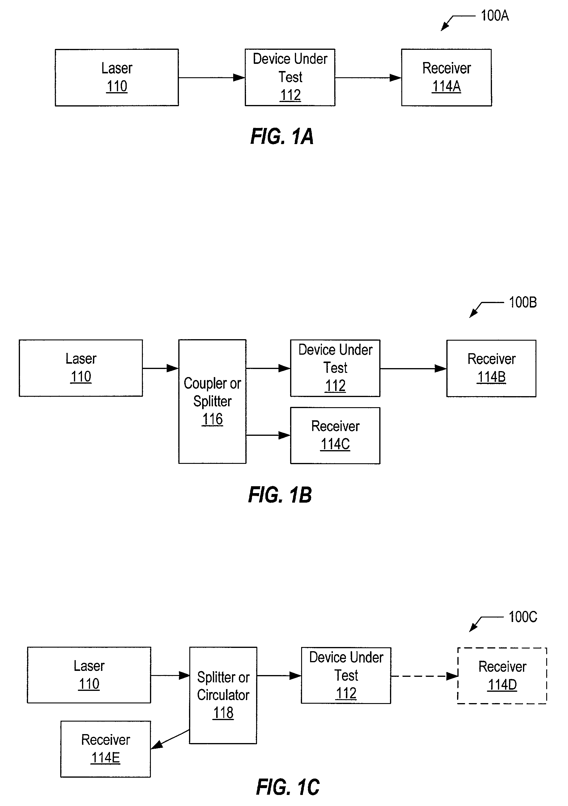
[0019] Before describing various embodiments of an optical receiver that includes a dual gain path amplifier, several systems that may include such an optical receiver will be discussed. FIGS. 1A-1C show typical measurement systems that may be used to characterize an optical component. In some embodiments of the systems shown in FIGS. 1A-1C, the optical component or device under test (DUT) 112 may include a coupler, combiner, splitter, attenuator, isolator, circulator, multiplexer, demultiplexer, interleaver, or wavelength filter.

[0020] FIG. 1A shows a system that may be used to measure the transmission characteristics of an optical component 112. In FIG. 1A, a laser 110 provides an input to DUT 112 and the output from that device is received by receiver 114A. The optical stimuli provided by laser 110 may sweep across a range of wavelengths, allowing the transmission of the component 112 to be characterized as a function of wavelength.

[0021] In FIG. 1B, a system that may be used to ...


PUM


Abstract

An optical receiver may include a photodetector that is configured to generate an electrical signal in response to detecting an optical signal, a first gain path coupled to receive and amplify the electrical signal generated by the photodetector, and a second gain path coupled to receive and amplify the electrical signal generated by the photodetector. The second gain path may have a higher gain than the first gain path. The two gain paths may be configured to amplify the electrical signal independently of each other. The optical receiver may also include a switch that selectably outputs an amplified electrical signal from one of the gain paths based on a magnitude of a signal corresponding to the optical signal.

Description

[0001] 1. Field of the Invention[0002] This invention relates to optical systems and, more particularly, to amplifier systems for use in optical receivers.[0003] 2. Description of the Related Art[0004] Fiber optic WDM (Wavelength Division Multiplexing) and DWDM (Dense WDM) systems are increasingly using more channels, narrower channel spacing, and wider wavelength ranges. As fiber optic systems such as these become more complex, it becomes increasingly important to characterize the wavelength-dependent optical properties of both broadband network components (e.g., couplers, combiners, splitters, attenuators, isolators, circulators, etc.) and narrowband network components (e.g., multiplexers, demultiplexers, interleaves, wavelength filters, etc.). By characterizing the optical properties of components, properties such as wavelength flatness and polarization-dependent loss that may adversely affect network system performance may be identified. In narrowband devices, it may be particul...

Claims


Application Information

Patent Timeline
IPC IPC(8): G01M11/00H04B10/158
CPCH04B10/6933G01M11/33
Inventor DAVIDSON, ANDREW
Owner NEWPORT CORP
Why Eureka
Try Eureka