
System for installation

a technology for installing systems and sensors, applied in the field of installation systems, can solve the problems of reducing the performance of the system, unable to adapt the image processing algorithms to the current installation/placement of the sensor, and the switch cannot be set in a limited number of positions, so as to save processor power

Inactive Publication Date: 2003-04-17
SECUMANAGEMENT
View PDF5 Cites 18 Cited by
  • Summary
  • Abstract
  • Description
  • Claims
  • Application Information

AI Technical Summary

Benefits of technology

[0019] One thing that separates the different applications is the function in the different sub-locations when the monitoring unit is operating. An advantage of the invention is that a person carrying out the installation does not need to have special knowledge to install the monitoring unit for different applications. This enables quicker and easier assembly and installation and, as a result, the costs for installation are reduced.
[0020] Another advantage of the system is that the definition of the sub-location will be more exact since the definition of the desired sub-location in the monitored location can be made in physical reality and transferred to the "the image world" of the monitoring unit. The word "image world" means how the monitoring unit perceives the physical reality. This causes the monitoring unit in operation to carry out a more thorough analysis of a recorded image, which in turn causes the monitoring result to be more secure and more reliable.
[0021] In one embodiment of the system, the monitoring unit further comprises means for receiving a signal containing information which identifies or qualifies said position.
[0022] The signal can contain information about what type of pattern the position defines. The pattern reflects the shape of a sub-location. If a pattern is defined by several points, the signal can contain information about to what point in the pattern the current position relates.
[0023] The monitoring unit can initially possess information about what pattern is to be created, and the information received by the signal can contain information about to what point in this pattern a detected position corresponds.
[0024] An advantage of the receiving the signal containing this information is that the monitoring unit quickly and unambiguously receives information about how the detected position is to be interpreted. The monitoring unit does not need to guess or calculate what pattern the position represents, thus saving processor power.

Problems solved by technology

For example, preselected values can be used, but a problem is that the parameters cannot be changed to adapt the image processing algorithms to the current installation / placement of the sensor.
If this is not accomplished, the performance of the system is reduced.
A disadvantage of this technique is that the switch can only be set in a limited number of positions.
This can be complicated and time-consuming and less accurate.
A disadvantage of this solution is that it requires special and advanced computer equipment and knowledge of the functions of the equipment in order to enable the person carrying out the installation to install a monitoring system.
It also requires special communication interfaces and contacts to connect the computer to the system, which causes extra installation work and increased costs.
Further it can be difficult in practice to exactly mark intended positions on the display, for example with a mouse, for instance due to insufficient contrast or inexact rendition on the display.
For example, in one sub-location a moving object can be allowed and movement detection is allowed in this location but in another sub-location no such object is allowed and movement detection in this location will cause an alarm.
The same remote device can be used for different applications, which results in lower manufacturing cost.
Additionally the cost for the system becomes lower by integrating two separate units.
This decreases the cost of the system.

Method used


Image

  • System for installation
  • System for installation
  • System for installation

Examples


first embodiment

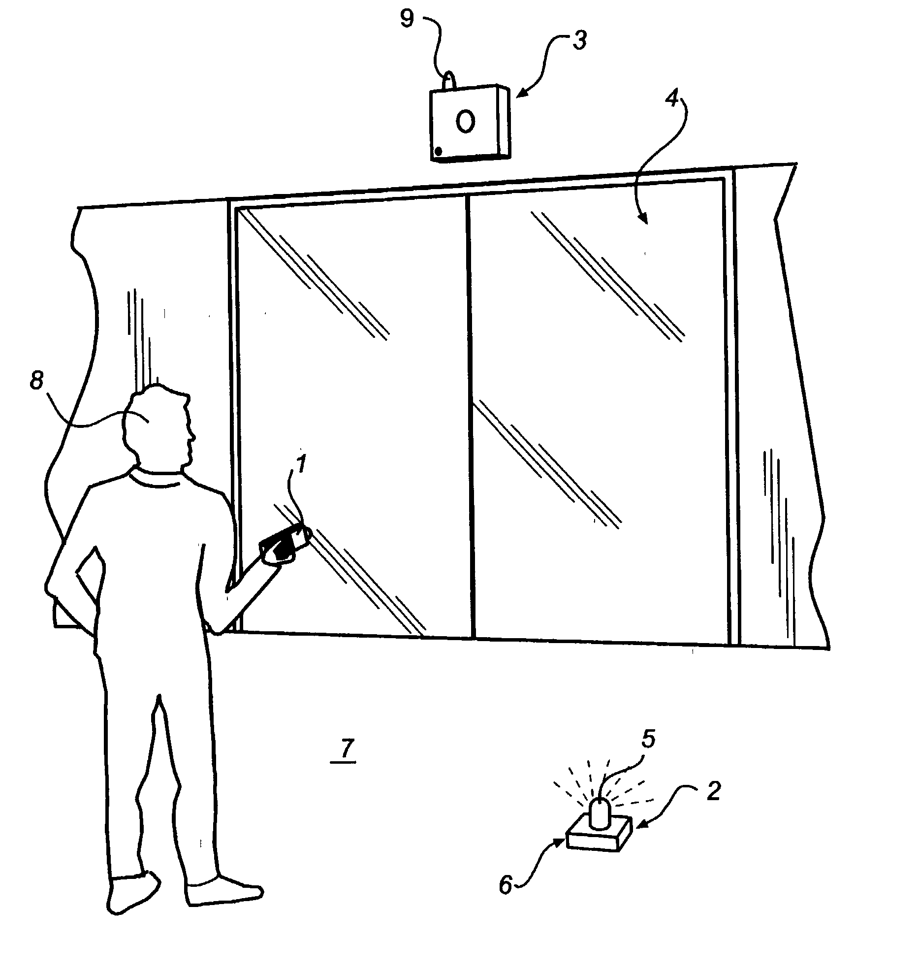
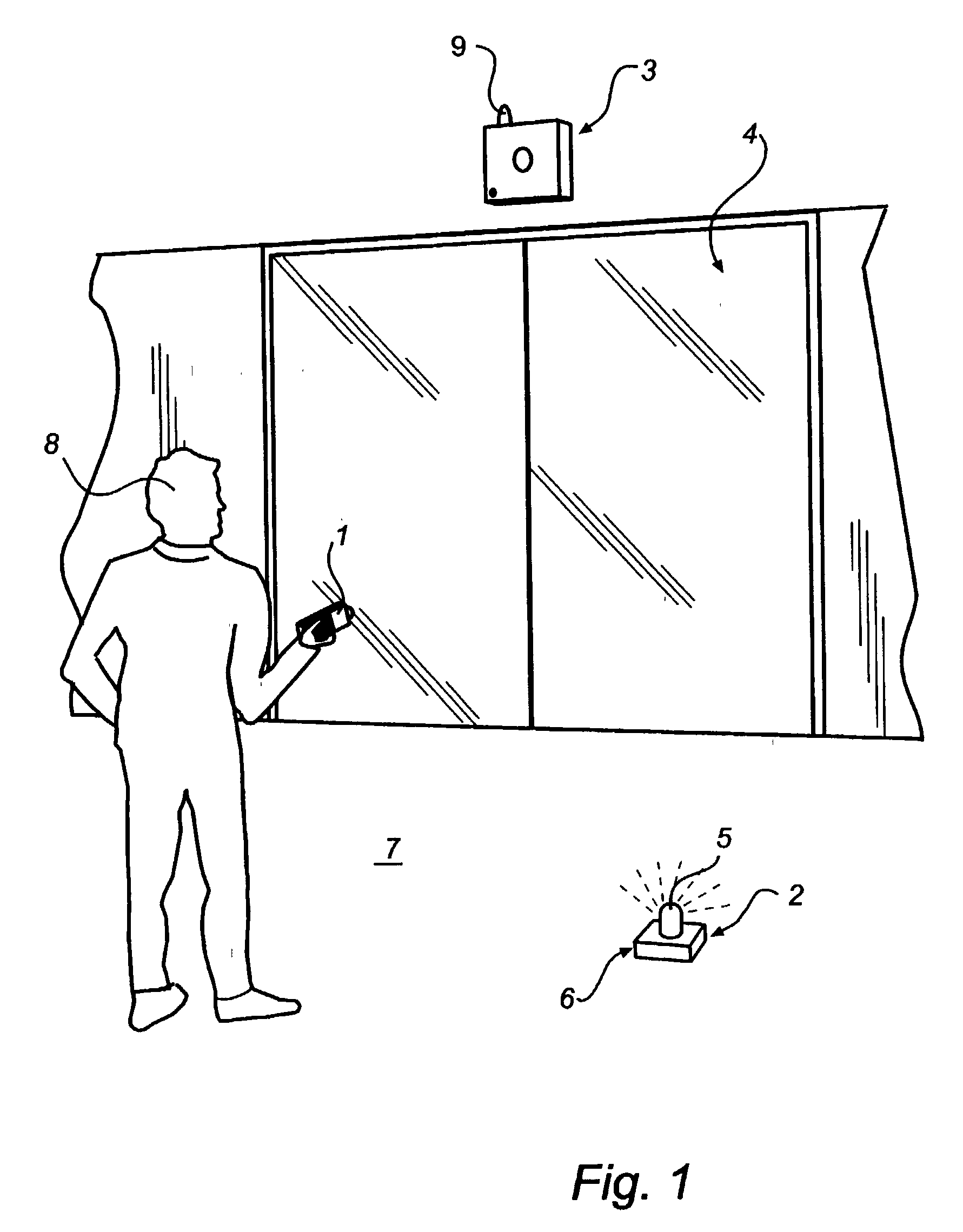
[0058] FIG. 1 is a perspective view of the system for installation according to the The system comprises a remote arrangement 1 sending a signal containing information regarding the position of a marker 2 on a base 7 to a monitoring unit 3.

[0059] The marker 2 may comprise a lamp 5 with an intense circular point-source light, such as a light emitting diode. The lamp 5 can be mounted on top of a box 6 provided with a matt black tarnish surface surrounding the lamp. The lamp blinks with a predetermined frequency which can be 2 times per second. The box 6 is formed with a flat side so that a person carrying out the installation can put it on the base 7 in order to mark a position. A person 8 carrying out the installation controls the remote arrangement 1 and moves the marker 2 to different positions on the base 7.

[0060] The monitoring unit 3 is arranged above a door arrangement 4 and controls opening / closing of the same. The door arrangement 4 is in this case a sliding door.

[0061] FIG....

second embodiment

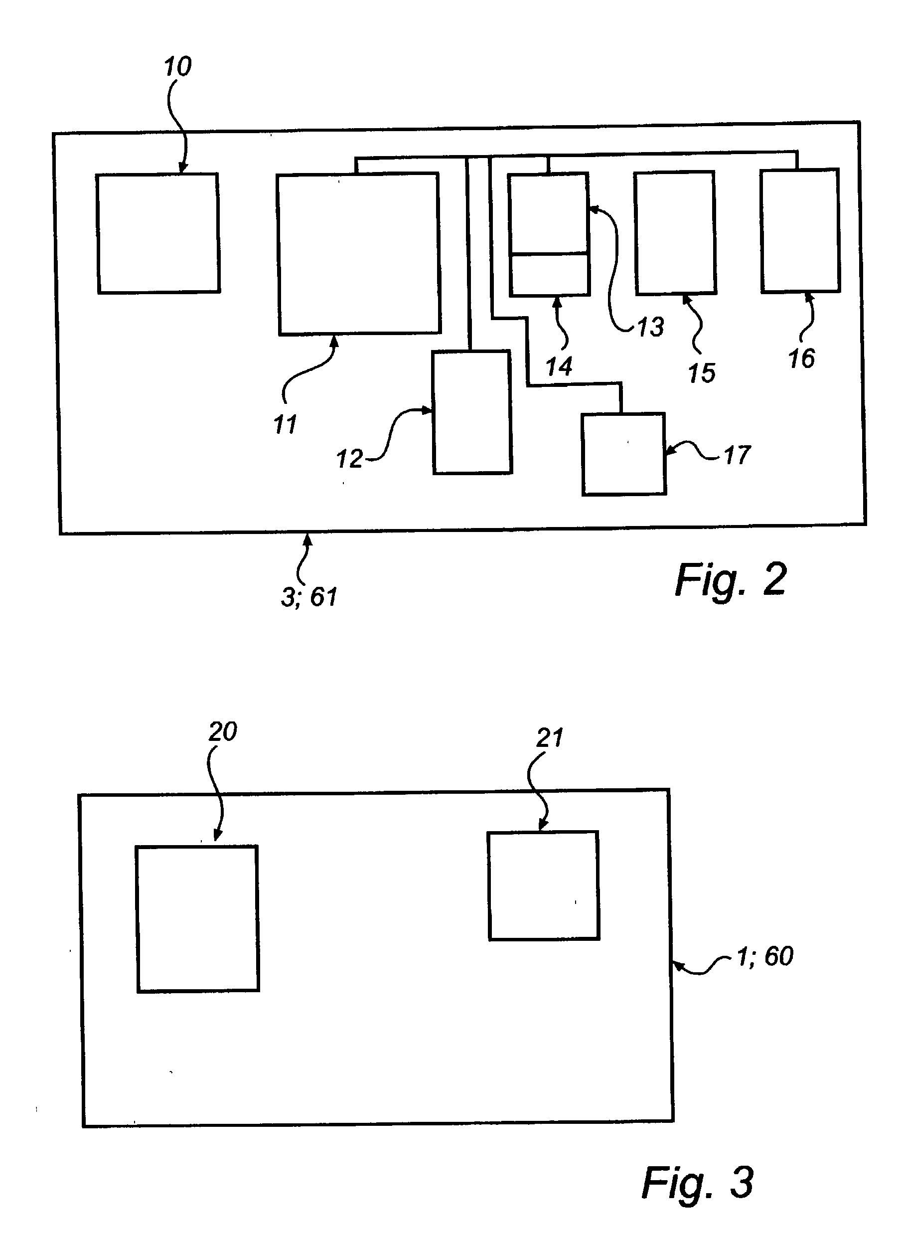
[0081] A second embodiment is shown in FIG. 6 and the monitoring unit works in a similar way as described above with reference to FIG. 5. Also the remote arrangement can work as described above with reference to FIG. 3 and FIG. 4 except for the marker which is now integrated with the remote arrangement as shown in FIG. 6. The remote arrangement 60 can be an ordinary remote control of the type as used for TV receivers. The remote arrangement 60 itself is placed on or held against the base. The remote arrangement 60 transmits a signal by means of an IR transmitter 65 to a monitoring unit 61 with IR pulses. The IR transmitter 65 can advantageously be realized as a commercially available light emitting diode (LED) with a wavelength in the infrared part of the spectrum.

[0082] The monitoring unit 61 receives the signal by means of an IR receiver 64. The monitoring unit 61 is also in this embodiment arranged to control the opening / closing of a sliding door 62. The same IR transmitter 65 us...


PUM


Abstract

A method and system for installation of a monitoring unit. The monitoring unit comprises a photosensitive sensor for recording images of a monitored location. The system further comprises a light emitting element. The monitoring unit is arranged to detect the position of the light emitting element in a recorded image and by means of said position specify a sub-location within the monitored location.

Description

[0001] This application is related to, and claims the benefit of, a previously filed U.S. provisional patent application, titled "System for Installation," application No. 60 / 328,644, filed Oct. 10, 2001.[0002] This invention relates to a method and a system for installation of a monitoring unit incorporated in the system. The monitoring unit comprises a photosensitive sensor for recording images of a monitored location. The invention also relates to an device for installation, a monitoring unit and a computer program product.PRIOR ART[0003] Different types of monitoring system with photosensitive sensors (digital cameras) are used today in different applications such as burglary surveillance. The sensor records images of a location that is to be monitored.[0004] The monitored location may be divided into different sub-locations within which different functions and criteria apply. These sub-locations can be defined by one or more coordinates in the image. The appearance and function...

Claims


Application Information

Patent Timeline
Patent Type & Authority Applications(United States)
IPC IPC(8): G08B13/194
CPCG08B13/19602G08B13/1968G08B13/19652G08B13/19615
Inventor ESPING, STEFANGUSTAFSSON, PETERHOVANG, DANELFVING, MATSAKHLAGI, NOROZ
Owner SECUMANAGEMENT
Learn More