Lens optical system

a technology of optical system and lens, applied in the field of lens optical system, can solve the problems of optical system designed for white light, wavelength-dependent diffraction efficiency of diffraction grating, and inability to meet the optical requirements of the system,

Inactive Publication Date: 2003-04-24
MINOLTA CO LTD
View PDF0 Cites 72 Cited by
  • Summary
  • Abstract
  • Description
  • Claims
  • Application Information

AI Technical Summary

Problems solved by technology

Although a diffractive lens element has useful properties as described above, it also suffers from problems resulting from the fact that the diffraction efficiency of the diffraction grating is wavelength-dependent.
This causes ghosts, and thereby degrades imaging performance.
In particular, an optical system designed for white light, i.e. one that needs to cope with a wide range of wavelengths, suffers greatly from this problem.
This degrades the transfer accuracy of the blaze shape.
If the lower limit of Condition (1) is exceeded, the degree to which the diffractive lens element needs to correct chromatic aberration becomes unduly high, and thus the blaze vertex angle of the diffra

Method used


Image

  • Lens optical system
  • Lens optical system
  • Lens optical system

Examples


embodiment 5

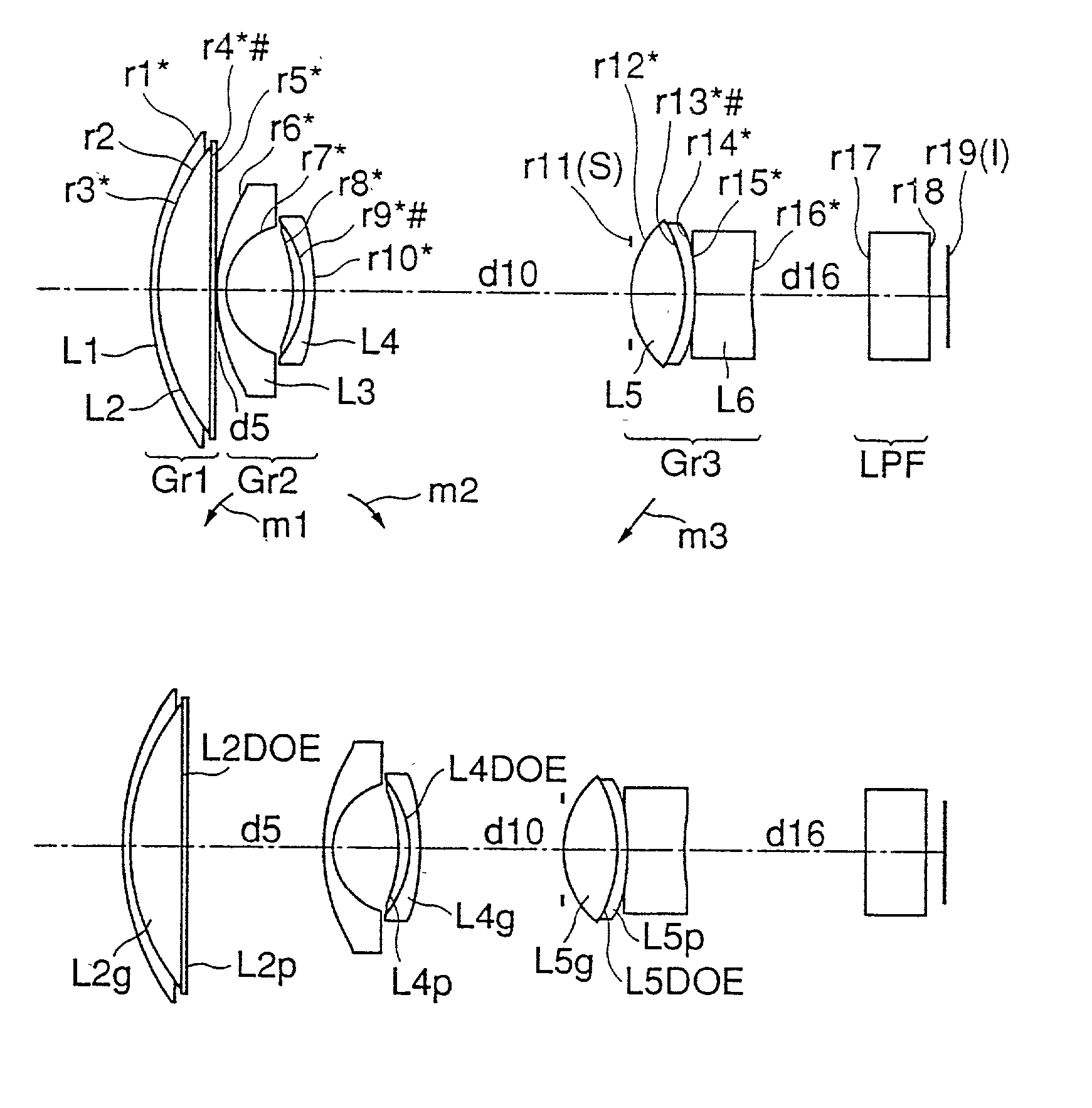
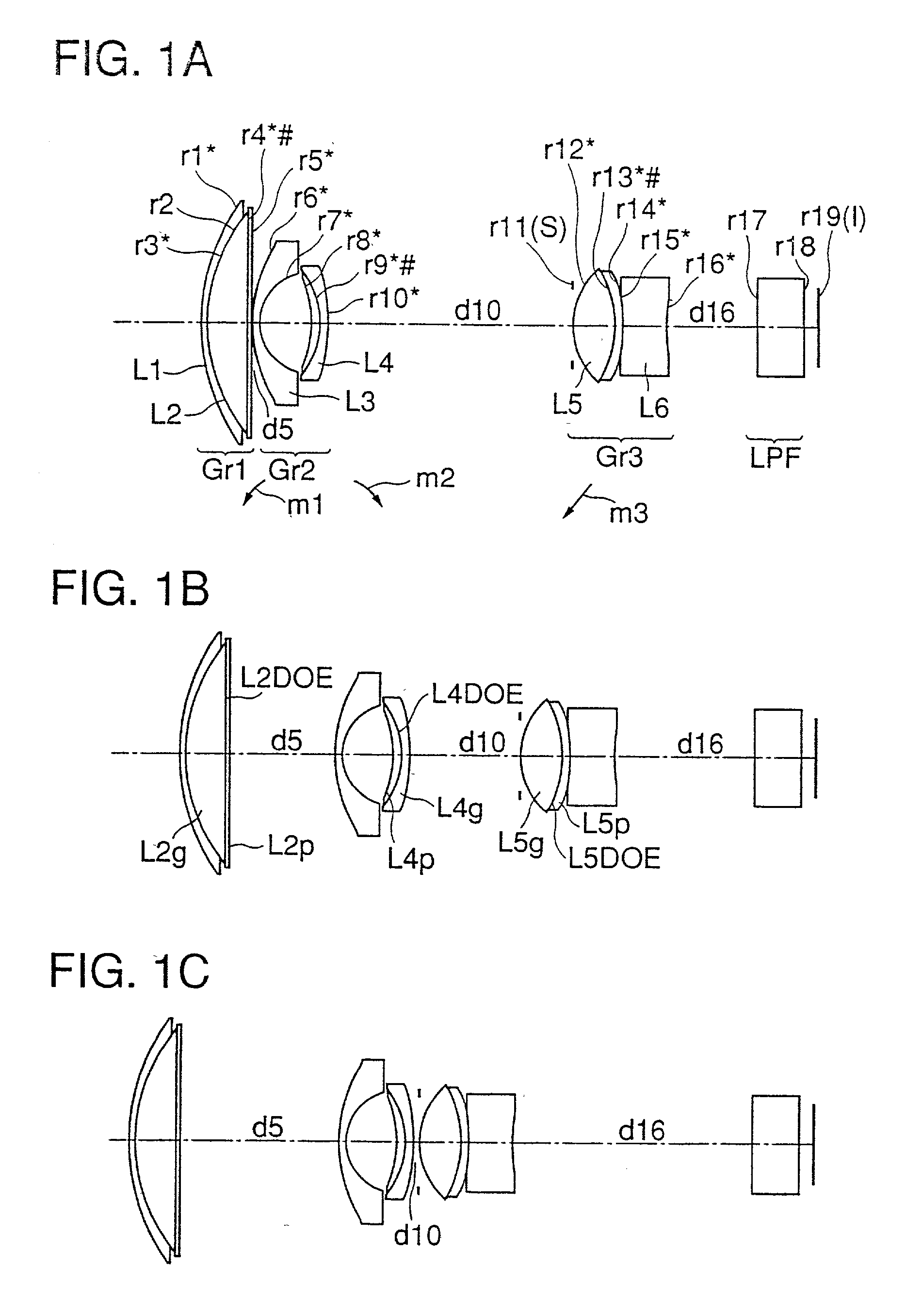
[0100] The lens optical system of the fifth embodiment is built as a three-unit zoom lens system that is composed of, from the object side, a first lens unit (Gr1) having a negative optical power, a second lens unit (Gr2) having a positive optical power, and a third lens unit (Gr3) having a positive optical power, wherein zooming is performed by varying the distance between the first and second lens units (Gr1 and Gr2) and so forth. In this lens optical system, between the second and third lens units (Gr2 and Gr3), an aperture stop (S) is disposed that is kept in a fixed position together with the third lens unit (Gr3) during zooming. Moreover, a low-pass filter (LPF) is disposed at the image-plane (I) side end of the lens optical system.

[0101] In the lens optical system of the fifth embodiment (FIGS. 12A to 12C), the lens units are each composed, from the object side, as follows. The first lens unit (Gr1) is composed of a negative biconcave lens element and a positive meniscus lens...

example 5

[0119] Hereinafter, an example of a lens optical system embodying the present invention will be presented with reference to its construction data, graphic representations of aberrations, and other data. Table 9 lists the construction data of Example 5, which corresponds to the fifth embodiment described above and has a lens arrangement as shown in FIGS. 12A, 12B, and 12C. Table 10 lists the construction data of Comparison Example 2, which corresponds to Example 5 but has a lens arrangement as shown in FIGS. 14A, 14B, and 14C (i.e. having no diffraction grating).

[0120] In the construction data of each example, ri (i=1, 2, 3, . . . ) represents the radius of curvature of the ith surface counted from the object side, di (i=1, 2, 3, . . . ) represents the ith axial distance counted from the object side, and Ni (i=1, 2, 3, . . . ) and vi (i=1, 2, 3, . . . ) respectively represent the refractive index for the d line and the Abbe number of the ith optical element counted from the object si...

embodiment 6

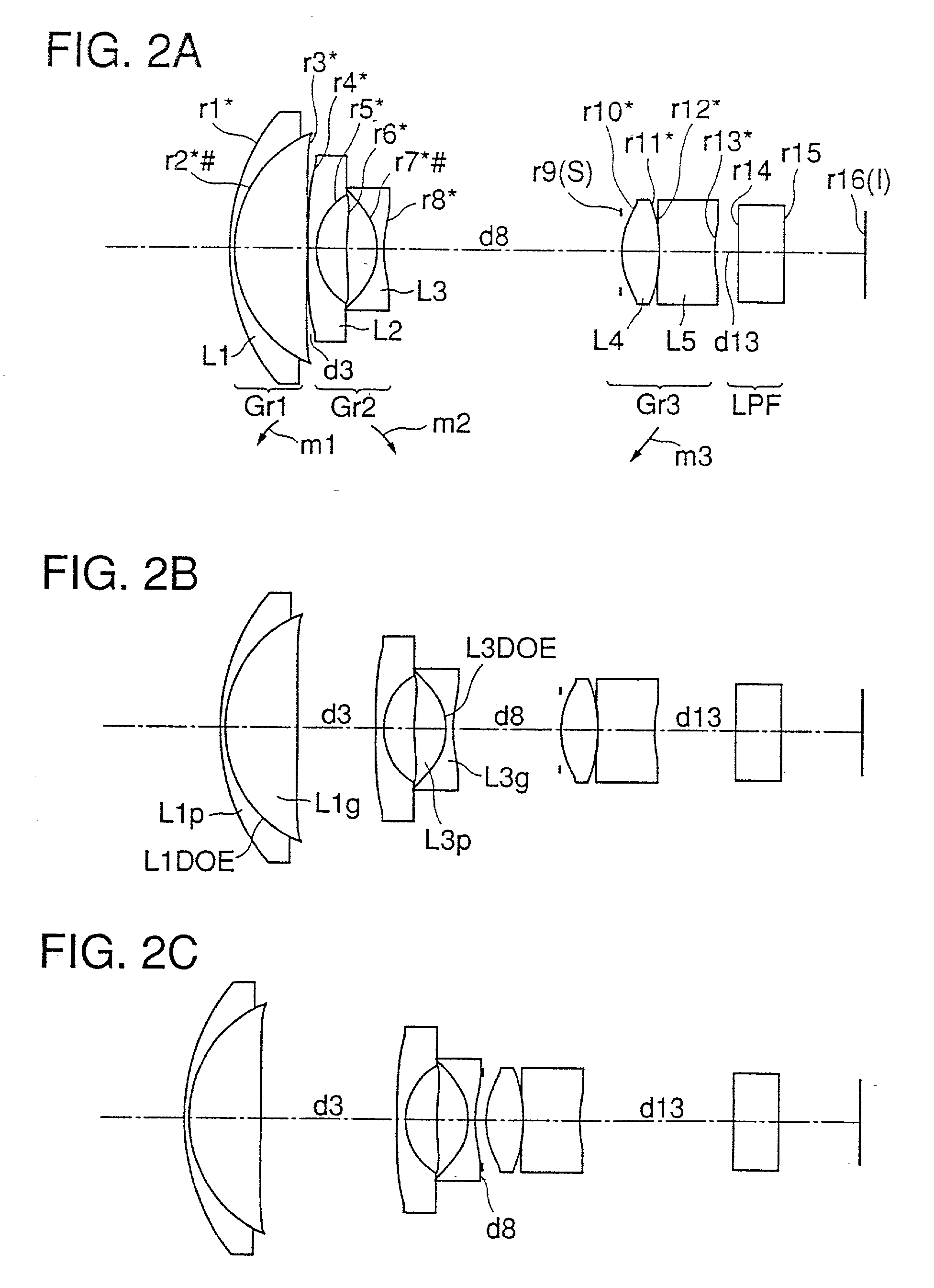
[0149] The lens optical system of the sixth embodiment is built as a three-unit zoom lens system that is composed of, from the object side, a first lens unit (Gr1) having a positive optical power, a second lens unit (Gr2) having a negative optical power, and a third lens unit (Gr3) having a positive optical power, wherein zooming is performed by varying the distance between the first and second lens units (Gr1 and Gr2) and so forth. In this lens optical system, between the second and third lens units (Gr2 and Gr3), an aperture stop (S) is disposed that moves together with the third lens unit (Gr3) during zooming. Moreover, a low-pass filter (LPF) is disposed at the image-plane (I) side end of the lens optical system.

[0150] In the lens optical system of the sixth embodiment (FIGS. 17A to 17C), the lens units are each composed, from the object side, as follows. The first lens unit (Gr1) is composed of a cemented lens element formed by cementing together a negative meniscus lens elemen...


PUM


Abstract

A lens optical system is provided with a cemented lens element formed by cementing two constituent lens elements made of different optical materials together, with a diffractive optical surface formed at the cementing interface between the two constituent lens elements. The two constituent lens elements have at their respective interfaces with air a radius of curvature different from the radius of curvature that they have at the cementing interface.

Description

[0001] This application is a continuation-in-part of U.S. patent application Ser. No. 09 / 294,385, entitled "A Lens Optical System", filed on Apr. 20, 1999, the disclosure of which is expressly incorporated herein by reference.BACKGROUND OF TIE INVENTION[0002] 1. Field of the Invention[0003] The present invention relates to a lens optical system, and more particularly to a lens optical system that employs a cemented lens element having a diffraction grating.[0004] 2. Description of the Prior Art[0005] A lens element that has a light-condensing ability offered by a diffraction grating formed thereon (hereafter such a lens element will be referred to as a diffractive lens element) has useful optical properties that are not found in a well-known refractive lens element. For example, a diffractive lens element offers the following advantages. First, by providing a diffractive lens element on a lens surface of an ordinary refractive lens element, it is possible to give a single lens eleme...

Claims


Application Information

Patent Timeline
IPC IPC(8): G02B5/18
CPCG02B27/4211G02B5/1814
Inventor OHMORI, SHIGETOORI, YUICHIRO
Owner MINOLTA CO LTD
Why Eureka
Try Eureka