
Systems and processes for refining a registered map of a body cavity

Inactive Publication Date: 2003-04-24
BOSTON SCI SCIMED INC
View PDF0 Cites 160 Cited by
  • Summary
  • Abstract
  • Description
  • Claims
  • Application Information

AI Technical Summary

Benefits of technology

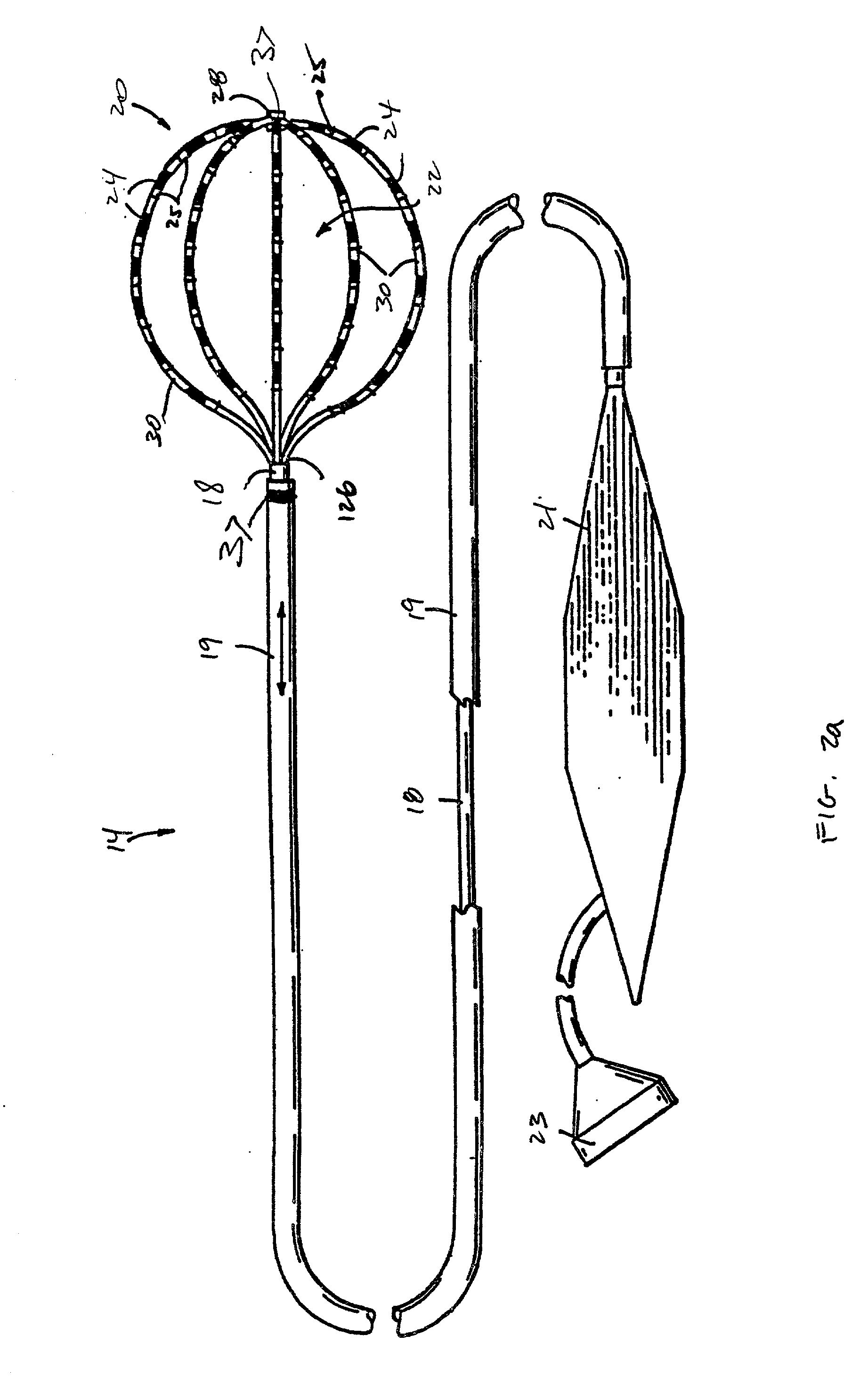
0014] In a third aspect of the present invention, a system for mapping a body cavity is provided. The system includes a first probe having a distal portion carrying a plurality of mapping elements and one or more location elements, and a second probe having a distal portion carrying a mapping element and a location element. In one embodiment, the first probe includes a 3-D catheter structure to carry the plurality of mapping elements. In an embodiment of this first probe, the 3-D catheter structure is 40 millimeters or less in size. A mapping processing subsystem is provided that is in communication with the plurality of mapping elements and the mapping element. The mapping processing subsystem is configured for generating a map by detecting information local to the body cavity using the plurality of mapping elements and the mapping element. A location determination subsystem in communication with the one or more location elements and the location element determines absolute positions of the plurality of mapping ele

Problems solved by technology

In practice, however, current minimally invasive mapping techniques do not ensure that an identified target site will be accurately or easily relocated.
One problem, however, occurs with mapping catheters having relatively small mapping element carrying structures, e.g., 3-D catheter structures that are 40 mm in diameter or smaller.
In these cases, it is difficult to place location elements adjacent all of the mapping elements, and sometimes even adjacent a select few of the mapping elements.
Thus, generating a three dimensional map is made difficult.
Another problem occurs as a result of the discrete nature of the mapping elements.
Oftentimes, critical information is missed between the mapping elements, resulting in a map that, although corresponding to the three-dimensional structure of the heart or other organ, does not accurately identify target sites.

Method used


Image

  • Systems and processes for refining a registered map of a body cavity
  • Systems and processes for refining a registered map of a body cavity
  • Systems and processes for refining a registered map of a body cavity

Examples


Embodiment Construction

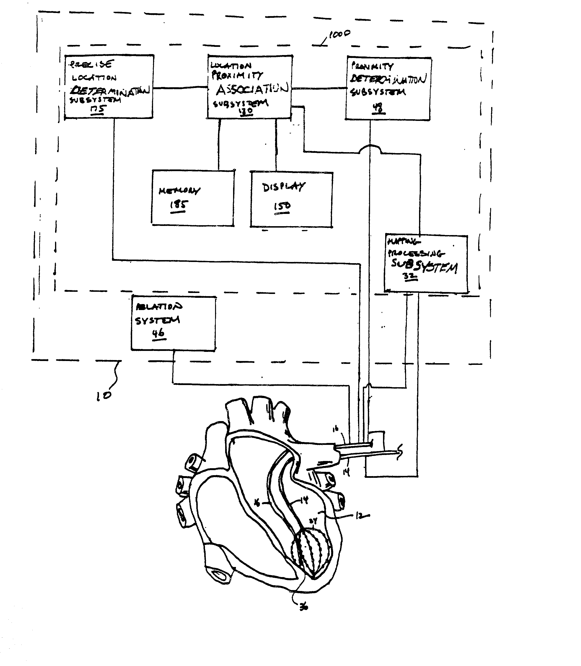
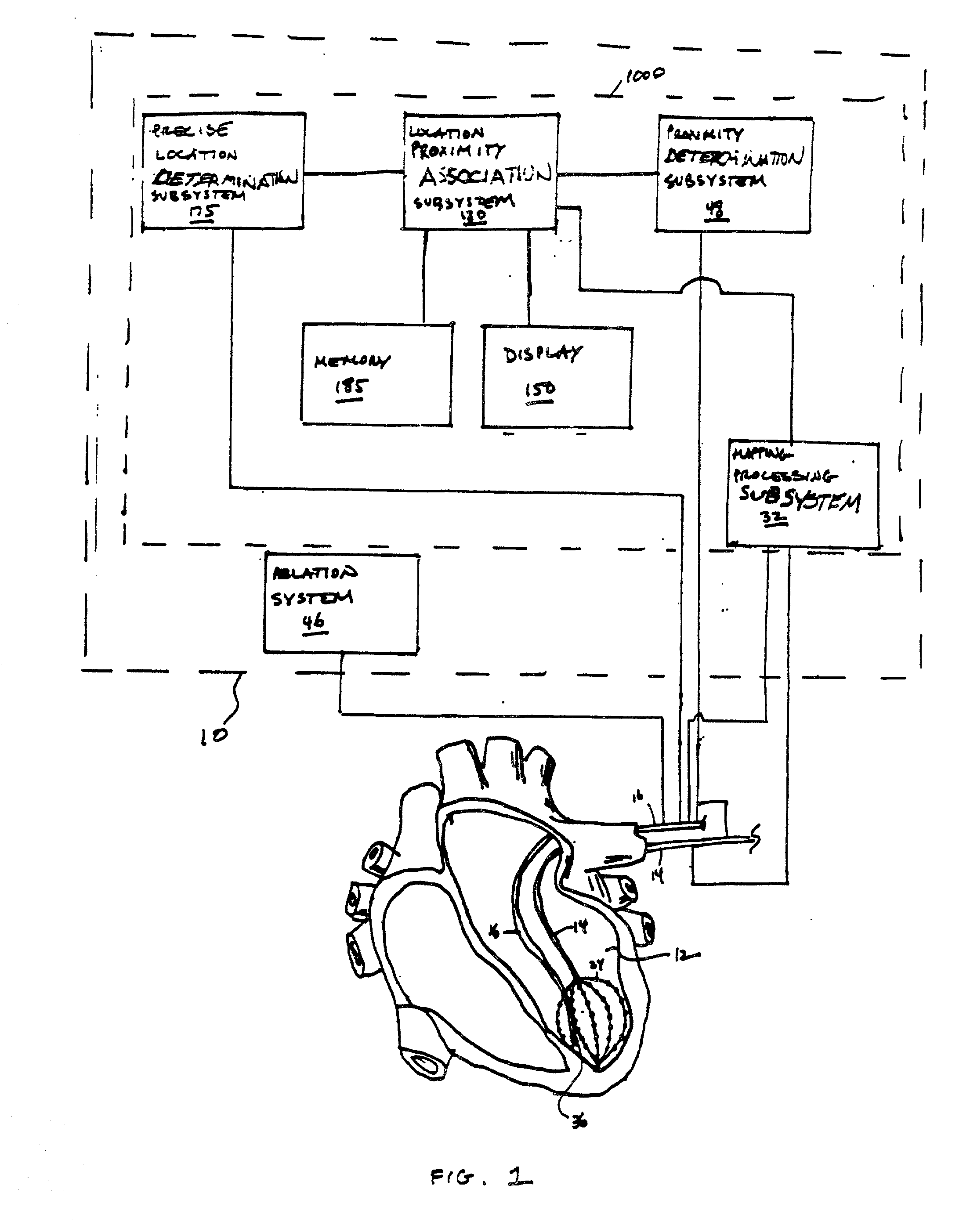
[0033] FIG. 1 illustrates the components of a system 10 of the present invention for mapping a three-dimensional reference coordinate system, e.g., a volume or other three-dimensional space in a patient's body, and for accessing a targeted region in the three-dimensional coordinate system for performing diagnostic or therapeutic procedures. The embodiment illustrated in FIG. 1 shows the system 10 for mapping a three-dimensional coordinate system within a heart and for being used for ablating heart tissue, which is one use for which the invention is well suited. Nevertheless, it should be appreciated that the invention is applicable for use in other applications. For example, the various aspects of the invention have application in procedures for ablating tissue in the prostate, brain, gall bladder, uterus, esophagus and other regions of the body. Additionally, it should be appreciated that the invention is applicable for use in drug therapy applications where a therapeutic agent is ...


PUM


Abstract

A process of refining a map of a body cavity includes positioning a first probe and a second probe within the body cavity. Mapping elements on the first probe are used to gather local information from a plurality of locations along the body cavity. The absolute locations of the mapping elements are registered in a three-dimensional coordinate system, and are associated with the local information to generate the map. A mapping element on the second probe is then used to gather information local to a location between the plurality of locations along the body cavity. The absolute location of the mapping element is registered in the three-dimensional system and associated with the local information to refine the map.

Description

FIELD OF THE INVENTION[0001] The invention relates to systems and methods for guiding and locating diagnostic or therapeutic elements on medical instruments positioned in a body.BACKGROUND OF THE INVENTION[0002] The use of invasive medical devices, such as catheters and laparoscopes in order to gain access into interior regions or spaces of the body for performing diagnostic and therapeutic procedures is well known. In such procedures, it is important for a physician or technician to be able to precisely position the device, including various functional elements located on the device, within the body in order to make contact with a desired body tissue location.[0003] For example, the need for precise control over the positioning of an invasive catheter or surgical probe is especially critical during procedures for testing or ablating myocardial tissue within the beating heart for treating cardiac rhythm disturbances. To perform such a procedure, the physician typically steers a cath...

Claims


Application Information

Patent Timeline
IPC IPC(8): A61B5/04A61B5/042A61B5/055A61B5/06A61B8/08A61B17/00A61B18/14A61B19/00
CPCA61B5/04011A61B2019/5454A61B5/055A61B5/06A61B5/063A61B5/6856A61B5/6858A61B8/0833A61B8/4254A61B18/1492A61B19/5244A61B2017/00053A61B2018/00214A61B2018/00839A61B2019/5251A61B2019/5263A61B2019/5278A61B5/0422A61B2034/2063A61B2090/3782A61B34/20A61B2034/2051A61B2090/3954A61B5/341A61B5/287
Inventor PANESCU, DORIN
Owner BOSTON SCI SCIMED INC
Learn More